Download
1 / 23
230 likes | 394 Vues
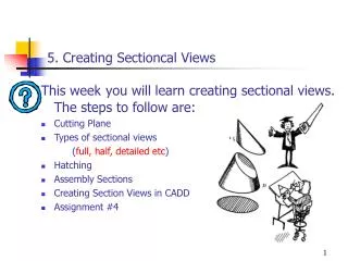
5. Creating Sectioncal Views. This week you will learn creating sectional views. The steps to follow are: Cutting Plane Types of sectional views ( full, half, detailed etc ) Hatching Assembly Sections Creating Section Views in CADD Assignment # 4. 5. Creating Sectioncal Views.

E N D
5. Creating Sectioncal Views This weekyou will learn creating sectional views. The steps to follow are: • Cutting Plane • Types of sectional views (full, half, detailed etc) • Hatching • Assembly Sections • Creating Section Views in CADD • Assignment #4
5. Creating Sectioncal Views Sectional views are usually produced (a) to clarify details of the object, (b) to illustrate internal features clearly, (c) to reduce the number of hidden-detail lines, (d) to facilitate the dimensioning of internal features, (e) to show the shape of the cross-section, (f) to show clearly the relative positions of parts forming an assembly.
5. Creating Sectioncal Views Cutting Plane Cutting plane lines typically lay in a view adjacent to the section view and represent the cutting path of the cross section
5. Creating Sectioncal Views Cutting Plane Line
5. Creating Sectioncal Views Full section Half section
5. Creating Sectioncal Views Offset section Local section Alligned section Revolved section
5. Creating Sectioncal Views Assembly Sections a) Views show how the parts fit together b) Individual components are identified by the use of numbers c) Adjacent components are hatched with a different properties (angle or scale) d) Standard components such as bolts, nuts are not hatched
5. Creating Sectioncal Views Using the BHATCH (Boundary Hatch) Command Command: BHATCH
5. Creating Sectioncal Views Boundary Hatch – 2
5. Creating Sectioncal Views Boundary Hatch – 3
5. Creating Sectioncal Views Boundary Hatch – 4
5. Creating Sectioncal Views Boundary Hatch – 5
5. Creating Sectioncal Views Boundary Hatch – 6
5. Creating Sectioncal Views Boundary Hatch – 7
5. Creating Sectioncal Views Using the HATCH Command Command: HATCH Enter a pattern name or [?/Solid/User defined]<ANSI31> Scale for pattern <1.0000>: Angle for pattern <0>: Select hatch boundaries or press ENTER for direct hatch option, Select objects: <Select objects to hatch> Select objects:
5. Creating Sectioncal Views HATCH – 2 Command: HATCH Enter a pattern name or [?/Solid/User defined]<ANSI31>S Select hatch boundaries or press ENTER for direct hatch option, Select objects: <Select objects to hatch> Select objects:
5. Creating Sectioncal Views HATCH – 3 Command: HATCH Enter a pattern name or [?/Solid/User defined]<ANSI31> Scale for pattern <1.0000>: Angle for pattern <0>: Select hatch boundaries or press ENTER for direct hatch option, Select objects: <Select objects to hatch> Select objects: <Select objects to hatch> Select objects:
5. Creating Sectioncal Views Command: _leader From point: _mid of To point: To point (Format/Annotation/Undo)<Annotation>: Annotation (or press ENTER for options): Tolerance/Copy/Block/None/<Mtext>: n Cutting Plane Line Drawing a Leader : 1st 2nd
5. Creating Sectioncal Views 1st 2nd Cutting Plane Line Typing Capital Letter
5. Creating Sectioncal Views Typing Capital Letter
5. Creating Sectioncal Views Next Week ; You will learn three dimensional design and solid modeling. The steps to follow are: • Geometrical Modelling • 3-D Modelling • Line or Wireframe Modelling • Surface Modelling • Solid Modelling • Assignment # 5
5. Creating Sectioncal Views Assignment # 4 • A front and top (plan) views of an Adjuster Base are given in the figure below. Draw the following views, in FIRST angle projection using a standard paper size: • A front view, • A top (plan) view, • Section A-A, B-B, and C-C. • Please include all dimensions in an appropriate way! Don’t forget to save it! Submit the assignmenton time!
5. Creating Sectioncal Views Assignment Procedure Open ISO_A3 template file Format the drawing file (linetype etc) Draw the sectional front view on A-A Complete the top view and the side view Give all necessary dimensions Fill in the title block (name, number, date etc) Submit your file via Ninova System