Download
1 / 3
70 likes | 304 Vues
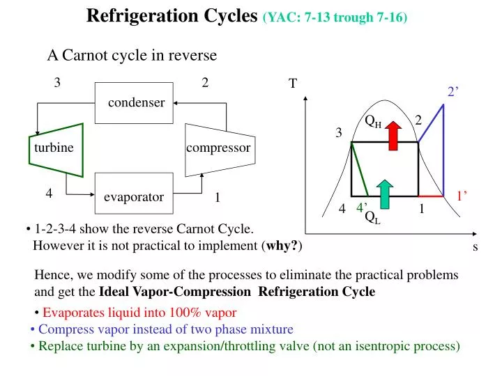
T. 2’. 3. 2. Q H. 2. condenser. 3. turbine. compressor. 1’. 4’. 4. 1. Q L. 4. evaporator. 1. s. Refrigeration Cycles (YAC: 7-13 trough 7-16). A Carnot cycle in reverse. 1-2-3-4 show the reverse Carnot Cycle. However it is not practical to implement ( why? ).

E N D
T 2’ 3 2 QH 2 condenser 3 turbine compressor 1’ 4’ 4 1 QL 4 evaporator 1 s Refrigeration Cycles (YAC: 7-13 trough 7-16) A Carnot cycle in reverse • 1-2-3-4 show the reverse Carnot Cycle. • However it is not practical to implement (why?) Hence, we modify some of the processes to eliminate the practical problems and get the Ideal Vapor-Compression Refrigeration Cycle • Evaporates liquid into 100% vapor • Compress vapor instead of two phase mixture • Replace turbine by an expansion/throttling valve (not an isentropic process)
Some Considerations • In order to produce reasonable heat transfer, the temperature difference should be as high as possible ( > 10°C). Therefore, in the evaporator the temperature should be as low as possible. It can be achieved by reducing the pressure. Problem: If the pressures is too low (below atmospheric pressure) then the probability of air leakage into the system increases. E.g: at atmospheric pressure, refrigerant 134 has a saturation temp. of -26.43°C. • The most common refrigerants, CCl2F2, Freon-12 (CFCs) are detrimental to the ozone (O3) layer. This leads to the penetration of more ultraviolet radiation into the earth atmosphere. Solution: replaced by Refrigerant 134a, CF2FCF3. • Heat pumps and air conditioners have the same mechanical components. Therefore, a combined system to meet both heating and cooling requirements. Just reverse the cycle such that the evaporator becomes the condenser, and the condenser becomes evaporator. (Ideal in areas where large cooling load is needed during summer and relatively small heating load during winter) • Recall that: COPrefrig = QL/ Wnet, in and COPheat pump = QH/ Wnet, in
A significant reduction in pressure can be achieved by introducing a restriction into the flow line. The restriction can be a partially-opened valve, or a porous plug, or a capillary tube. • Enthalpy (internal energy + flow work) is a constant going through a throttling process: h1=h2(see YAC 4-3 for more on throttling valves) • Throttling processes lead to a pressure drop without producing any work – unlike turbines. Throttling Process Example: Saturated liquid refrigerant-134a enters the throttling device at 1 MPa and exits at a lower pressure of 0.1 MPa. Determine the temperature drop during this process. At inlet: from table A-9, T1=Tsat@1MPa =39.39°C, h1=hf @1MPa=105.29 kJ/kg At outlet: h1=h2, P2=0.1 MPa, T2=-26.43°C hf=16.29, hfg=215.06, x=(h2-hf)/hfg=0.414 (41.4% of the refrigerant-134a vaporizes during the throttling process). Question: where does the energy come from to vaporize the refrigerant? DT = -26.43-39.39 = -65.82°C, temperature drops significantly during the throttling process.