Tower configuration
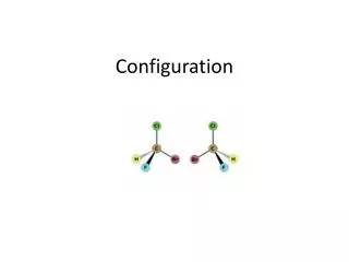
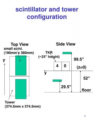
1. 3. 5. 5. 2. ∆. 0/1. 7. 7. 5. 6. 4. Tower configuration. Sensors and Actuators 1 Mechanical level sensor 2 Pressure level sensor 3 Visual level sensor 4 Controlled pump 5 Locations for : 5.1 Flow sensor 5.2 Controlled on/off valve 5.3 Controlled variable valve


Tower configuration
E N D
Presentation Transcript
1 3 5 5 2 ∆ 0/1 7 7 5 6 4 Tower configuration Sensors and Actuators 1 Mechanical level sensor 2 Pressure level sensor 3 Visual level sensor 4 Controlled pump 5 Locations for : 5.1 Flow sensor 5.2 Controlled on/off valve 5.3 Controlled variable valve 6 Location for outlet control valve (for final competition) 7 Manual valves (for configuration and test) Version 31-01-08
Two different • Pumps are proposed: • Low power pump • Medium power pump • Both use the same control circuitry Optical Fibers LED Opto- TRIAC 220 V Pump Commercial aquarium pumps are used. It is possible to adjust somewhat the pump power by using a simple dimmer such as those used for lights. As these pumps have important internal leakage, a one-way valve has been inserted to avoid reversal of the waterflow when the pump is stopped or runs at low power. Version 31-01-08
Overflow Prevention To be installed in February 2008 Version 31-01-08
10KΩ 10 turns 0-5V GND + 5V Mechanical Level Sensor Version 31-01-08
P -2 to 10 mV 0-5V GND + 5V * 500 Pressure Level Sensor Solid state pressure transducer Version 31-01-08
T Q = n/k.T Flow Meter Instantaneous measurement mode t Q = 1/k.t k = 752 pulses / liter 0/5V GND + 5V Hall effect sensor Integrating measurement mode n pulses Version 31-01-08
Waterpeilmeting met Webcam x cm Webcam (resolutie 640x480 pixels) niveau (n cm) PC Water Version 31-01-08
n=p*x/480 Waterpeilmeting met Webcam Digitaal Beeld afkomstig van de webcam Lucht/glas pixelwaarde y water y 0 480 480 pixels Absolute waarde van de gradient p pixels y 0 480 Detectievenster (manueel instelbaar) p wordt bepaald door te zoeken naar het maximum van de gradient magnitude. Detectie van de overgang tussen lucht en water: discrete gradient magnitude van de pixelwaarde in de y richting (binnen het detectievenster). Version 31-01-08
∆ USB 0/1 ∆ 0/1 5V sensor 4-20mA DC control Pulse frequency Fiber optic link 24V DC control Fiber optic link EIA serial link 0-5V signal Bus Slave pc Bus Slave gp Bus master Bus Slave pv Bus Slave fm EIA 485 instrumentation bus Control System Building Blocks Version 31-01-08
Bus Master • Interface between PC and EIA485 bus • Personal Computer Interface : • Serial EIA232 interface at 19200 b/s. • Data format : 8 bits/char, no parity, one stop bit. • EIA485 bidirectional bus : • Talk : from master to slave, Red bus led on. • Listen : from slave to master, Green bus led on. • Bus reset sequence : 0AH,0DH,0DH,0DH • Slave command : 0AH, 0DH, Command byte, Data byte. • Slave answer : 0DH, Slave ID byte, Answer byte. • Display : • Left display : Command byte • Right display : Data byte Version 31-01-08
Bus Master FSM Version 31-01-08
Slave module V 2.1 +12V - 12V +12V PIC RA0 - 12V RA1 RA2 Bb Ba RA3 RA4 +5V RC2 gnd 0 1 Data +5V gnd Lsb Command Id = msb Bus SlaveCommon module Version 31-01-08
Bus SlaveCommon module • Slave Commands : (0AH), 0DH, Command byte, Data Byte. • Command byte : • Four msb : Slave ID : • 1 to 14 each ID unique on one bus. • 15 = broadcast • Four lsb : Command code: • 0 = software reset • 1 to 15 : device specific command. • Most devices recognize only one command byte • Data byte : • Any value between 0 and 255 • Meaning is device specific Version 31-01-08
Bus SlaveCommon module • Slave Answers : 0DH, Slave ID byte, Answer Byte. • Slave ID byte : • Four msb : 0000 • Reserved for future developments. • Four lsb : Slave ID • Number between 1 and 14. • Answer byte : • Any value between 0 and 255 • Meaning is device specific • Broadcast messages are never answered Version 31-01-08
Bus SlaveCommon module • Red LED Display • Left Display: last Command byte accepted by slave • Right Display : last Data byte accepted by slave • Green Decimal Display • Meaning is device specific • Usually related to the answer byte send by the slave Version 31-01-08
General Purpose Interface • Inputs • 0-5 V analog signal between RA0(+) and RA2(ref) • Outputs • On-off optical command on RA1 • On-off 24 V DC command on RA4 • Commands • 0 : software reset • 1 : copy data bits 1 and 4 onto RA ports 1 and 4 and measure input • 2 : measure analog input without affecting digital output • Answer • Rounded value of 8 most significant bits from AD converter. • Decimal display • Value of AD input in % of 5 V. • Device ID’s • First interface = 1; second interface = 9 Version 31-01-08
AD/DA Interface(not yet available) • Inputs • 0-5 V analog signal with differential buffer • Outputs • 0-5 V buffered analog output, with 1s integrator. • Commands • 0 : software reset • 1 : set analog output signal • Answer • Rounded value of 8 most significant bits from AD converter. • Decimal display • Value of AD output in % of 5 V. • Device ID’s • First interface = 4; second interface = C Version 31-01-08
t t t 10 mS 10 mS 10 mS Pump Control Version 31-01-08
Pump Control • Inputs • Optical 50 Hz signal from pump power module • Outputs • Optical 100 Hz triac firing pulses with adjustable delay after the 50 Hz reference input • Commands • 0 : software reset, switches off the pump. • 3 : sets adjustable delay in the range 0-176 (=B0H) steps of 51μS. The smallest delay results in maximal pump power. • Answer • Echo of the command data byte. • Decimal display • Value of firing delay in multiples of 100 μS. • Device ID’s • First interface = 2, no additional interfaces useful. Version 31-01-08
Proportional Valve Control • Inputs • none • Outputs • Valve control current, 4-20 mA. Valve is closed at 4 mA. • Commands • 0 : software reset, closes the valve. • 2 : sets valve current in steps of 0.1mA, 0 = 0 mA, . • Answer • Current through valve before command was received, expressed in multiples of 0.1mA. • Decimal display • Current in mA. • Device ID’s • First interface = 2; second interface = 10 (=AH) Version 31-01-08
Inputs Pulses from Dataflow compact flow transmitter Outputs none Commands 0 : software reset. 4 : request reading of the pulse counter Answer Time interval between successive pulse, in units of 0.4096 mS. 255 means underflow (out of time range) Decimal display Time interval, expressed in % of 100 mS Device ID’s First interface = 4; second interface = 12 (=CH) Flow Meter (Version 1.0) Version 31-01-08
Inputs Pulses from Dataflow compact flow transmitter Outputs none Commands 0 : software reset. 4 : data byte = 0:enable pulse duration measurement data byte = 1: enable pulse counting measurement Answer Mode 4.0 : pulse duration, in multiples of 0.4096 mS Mode 4.1 : Number of pulses in 105 mS. In both modes : FFH means “out of range” Decimal display In both modes : Fraction of full range in % Device ID’s First interface = 4; second interface = 12 (=CH) Flow Meter (Version 2.0, not yet available) Version 31-01-08
Prijslijst Version 31-01-08
Command Summary (1) Commands with ID = 15 (=FFH) are broadcasts. Slaves don’t generate answers to broadcast messages (2) Command 0 followed by any data byte resets the interface software and reads the ID switches. No answer is generated. Version 31-01-08