Download
1 / 20
200 likes | 344 Vues
PH4705/ET4305: A/D: Analogue to Digital Conversion. Digital World Background: Binary numbers, BCD, Octal, Hex Computer word size (8,16…..bits) Digital representation of an analogue signal is always an approximation. PH4705/ET4305: A/D: Analogue to Digital Conversion.

E N D
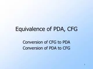
PH4705/ET4305:A/D: Analogue to Digital Conversion Digital World Background: Binary numbers, BCD, Octal, Hex Computer word size (8,16…..bits) Digital representation of an analogue signal is always an approximation
PH4705/ET4305:A/D: Analogue to Digital Conversion Key A/D Characteristics: Resolution Accuracy Quantization Error, noise Conversion Speed/Time of Reading Parallel, serial output A/D types: Traditional, modern
PH4705/ET4305:A/D: Analogue to Digital Conversion Resolution The number of bits in the output of an A/D converter defines its RESOLUTION Resolution is commonly considered in terms of the Least Significant Bit, LSB, Vfs=full scale voltage N=number of bits
PH4705/ET4305:A/D: Analogue to Digital Conversion A 16-bit converter operating with a full scale range of 5 V would have a LSB calculated as
PH4705/ET4305:A/D: Analogue to Digital Conversion Accuracy versus Resolution A: both low B: accurate (all on target) but low resolution C: high resolution (tight group) but not so accurate D: high resolution and accurate
PH4705/ET4305:A/D: Analogue to Digital Conversion Quantization Error Transfer function of an ideal 3 bit A/D. The straight line is analogue in analogue out The staircase is the best an A/D can do
PH4705/ET4305:A/D: Analogue to Digital Conversion Because the digital output must assume one of the available discrete binary codes there will be a deviation from the ideal whenever that code does not match the analogue value. This quantization error is ±½LSB Other sources of noise are still there, the aim is to keep them <±½LSB Jitter: The output of an A/D may constantly cycle ±1LSB
PH4705/ET4305:A/D: Analogue to Digital Conversion Conversion Speed/Time of Reading A further source of potential error is related to the dynamic behavior of A/D: A/D conversion takes time, during that time the analogue signal may have changed. Where in the time taken for conversion was the analogue input sampled? This is usually fixed by the clock signal of the A/D but exactly where is that? This time uncertainty is termed APERTURE ERROR.
PH4705/ET4305:A/D: Analogue to Digital Conversion Simple A/D: The counter starts at zero, the output of the D/A is a staircase that is compared with the analogue input by the comparator, when it equals (or exceeds) it the comparator output switches stopping the clock to the counter
PH4705/ET4305:A/D: Analogue to Digital Conversion Again using a 3bit A/D as Illustration. The analogue input is converted to 101 in 5 clock cycles. The disadvantage of this arrangement is that conversion time is not fixed, it is longer for higher Voltages.
PH4705/ET4305:A/D: Analogue to Digital Conversion Successive Approximation A/D: This get there faster. Bits in the counter are toggled from the MSB (most significant bit) end, so ½, ¼, 1/8 of full scale are added or subtracted until the input value is reached ( to within the resolution). The diagram again uses 3 bits to illustrate the principle.
PH4705/ET4305:A/D: Analogue to Digital Conversion Modern A/Ds use much more complex conversion techniques to achieve high accuracy fast. For discussion see Bill Klein’s article on the web site. To find out more Wikipedia is a good s tarting point.
PH4705/ET4305:A/D: Analogue to Digital Conversion A/D Data Output: How many bits? Depends on required speed of conversion, resolution required and complexity (cost). Typically between 8 and 16 bits, with 8 and 12 bits being common. (16 bits is, in most applications, much higher resolution than is necessary as ±1LSB represents and error of 0.00002% and other noise is very difficult to keep down to that level.)
PH4705/ET4305:A/D: Analogue to Digital Conversion A/D output cont: Parallel data output is common particularly in older designs and at higher resolutions. Some newer A/D chips have a serial output, they are intended for microprocessor and embedded systems and take advantage of the higher clock speeds of modern ICs.
PH4705/ET4305:A/D: Analogue to Digital Conversion Auxiliary circuits: Sample and Hold Fixes a time varying analogue signal whilst conversion takes place Analogue multiplexer Enables an A/D to sample more than one analogue input
PH4705/ET4305:A/D: Analogue to Digital Conversion An Analogue Multiplexer is simply a switch that connects multiple analogue inputs signals to a single output one at a time. It is used to concentrate analogue inputs into a single information stream for further processing, either because the analogue inputs change only slowly so need not be continuously monitored, or because the following processing is complex and the expense of a processor for each signal cannot be justified. Analogue multiplexers use FETs as switches and which input is connected to the output is usually determined by a digital address word. Typical IC devices have either 8 or 16 inputs.
PH4705/ET4305:A/D: Analogue to Digital Conversion IC analogue multiplexers come in two variants. For single ended or differential inputs (matching our two types of sensor circuit). The device shown is DG406 single ended and DG407 differential. Note the addressing a enable logic.
PH4705/ET4305:A/D: Analogue to Digital Conversion Another common IC is the DG408/409 with either 8 single ended or 4 differential inputs. Channel on-resistance: 100Ωmax, leakage (when off): 5nAmax, channel characteristics closely matched. Digital input TTL/CMOS compatible, Power supply ±18v max (dual or single, input voltage range- rail to rail, Low power 1.25mW max.
PH4705/ET4305:A/D: Analogue to Digital Conversion A typical application of an analogue multiplexer, gathering multiple analogue signals through a sample and hold and an analogue to digital converter into a digital data stream. The operating principle of the sample and hold is illustrated, a sample of the analogue input voltage is stored on the hold capacitor, which is impedance buffered by the Op Amps on either side. Sample/hold switching is coordinated with switching the multiplexer.
PH4705/ET4305:A/D: Analogue to Digital Conversion Typical devices and specification