Dual-axis, Duo Lateral Position Sensitive Detectors
230 likes | 515 Vues
Dual-axis, Duo Lateral Position Sensitive Detectors. Robin Dienhoffer State University of New York at Oswego Advisor: Dr. Sherry Yennello Cyclotron Institute, Texas A&M University. Outline. Particle Detectors Silicon Detectors Position Sensitive Detectors now

Dual-axis, Duo Lateral Position Sensitive Detectors
E N D
Presentation Transcript
Dual-axis, Duo LateralPosition Sensitive Detectors Robin Dienhoffer State University of New York at Oswego Advisor: Dr. Sherry Yennello Cyclotron Institute, Texas A&M University
Outline • Particle Detectors • Silicon Detectors • Position Sensitive Detectors now • New Position Sensitive Detector
Particle Detectors • Materials and forms used • Solid, liquid & gas • Various elements • Germanium, Cesium iodide, silicon, plastic… • Various Attributes • Stopping power • ΔE vs. E plots • Energy and position resolution • Cost • Ease of handling • Combining Detectors
Silicon Detectors • Not overly sensitive to humidity and operates well at room temperatures • Delicate, but not impossible to handle • Still expensive, but becoming more widely used • Band Gap
Band Gap • Energy difference between valance band and conduction band • Silicon is a good material to detect the particles that we work with • To get to the conduction band, approximately 2.8 eV are needed • To get a readable charge, electrons must be excited enough to “jump” to the conduction band • This charge is then collected by the charge collection strips to be converted to signals Conduction Band Band Gap Valance Band
What are PSDs? • PSD stands for Position Sensitive Detector • Collects deposited charge in such a way that the position of the particle can be determined • This will allow us a more thorough understanding of the underlying reaction mechanism that produced the charged particles
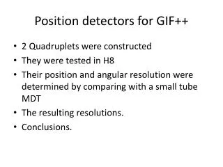
FAUST • The Forward Array Using Silicon Technology • Currently uses discrete detectors • Position information restricted to which detector was hit • Hoping to upgrade to PSDs, giving better position resolution
Some PSDs in Use • Pixilated Detectors • Strip detectors that use separated pads of Silicon to detect where the particles hit • The number of channels of electronics limit the feasibility of this option • Resistive Detectors • Dual-axis • Tetra-lateral • DADL
Dual-axis • Signal pulled from the edge centers • This results in circular pulling that must be adjusted through correcting algorithms
Dual-axis Tetra Lateral • Dual-axis Tetra lateral detector collects charge at all four of the corners on one face of the detector • This causes a pin-cushion effect which must, again, be accounted for using correction algorithm
Four Corner PSD – Dr. Tribble’s Group • Resistive sheet of Si on front and a non-resistive sheet on the back • resistive strips on front edges correct pincushion effect • Five signals- four on front and one on back (total energy)
Dual-axis, Duo Lateral • Dual-axis, duo lateral PSDs collect charge in a way which give position from both the front (horizontally) and the back (vertically). This method will lead to much less distortion than in previous models.
F2 B2 Front 1 Back 2 Guide wires for charge F1 B1 Front 2 Back 1 Charge collecting strips
Edge 1 Edge 2 L2 L1 L1 L2 Guide Wires L2 L1 Detecting Location Charge Collection WhenL1 = L2, both edges receive the equal charge, or Q1 = Q2 WhenL1 > L2, Edge 1 receives less charge, or Q1 < Q2 WhenL1 < L2, Edge 1 receives more charge, or Q1 > Q2
/\/\/\ /\/\/\ /\/\/\ Another Perspective V1 V2 Vo Vo = V1 + V2
Settings • Found that biasing the front to 40.0 volts and the back guard ring to 5.0 volts is the most effective to get a clear energy spectra and position graph • Shaping time of 1 μs or 3 μs gives both good energy and position resolution
228Th Energy Spectra 5.686 6.051 6.288 6.778 5.432 8.784
Beam Time: Ag + natAuΔE-E Graph Triton Deuteron Z = 3 Proton Z = 2 Z = 1
Hole Ratios Red = 1.20, 1.25 Green Red = 0.50, 0.50 Blue Green = 1.67, 1.60 Blue
Future Use • This PSD design is currently being optimized for the future FAUST upgrade • Micron Semiconductor is offering this detector to the scientific community at large
Acknowledgements • Dr. Sherry Yennello • SJY Group • REU Program • NSF, Grant _____ • Robert A. Welch Foundation, Grant A-1266 • DOE, Grant DE-FG03-93ER40773.