Manufacturing Processes
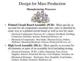
Manufacturing Processes. Chap. 23 - Machining of Other Shapes. Milling. Definition Generation of a surface by progressive chip removal. Workpiece is fed into rotating cutter rotating along various axes with respect to workpiece. Material removal rates are high as cutter has multiple teeth.

Manufacturing Processes
E N D
Presentation Transcript
Manufacturing Processes Chap. 23 - Machining of Other Shapes
Milling • Definition • Generation of a surface by progressive chip removal. • Workpiece is fed into rotating cutter rotating along various axes with respect to workpiece. • Material removal rates are high as cutter has multiple teeth. • One of the most versatile machining processes available. Can achieve great surface finish.
Milling Categories • Peripheral or Slab Milling: • Teeth located on the outside of the cutter body create surface. • Surface is parallel to cutter axis. (See Fig. 23.2) • Can make both flat and contoured surfaces (a function depending on cutter shape). • Cutting of horizontal surfaces on horizontal millling machine is called SLAB milling.
Peripheral Milling • Parameters • Feed per tooth ft (in inches per tooth) • Cutting Speed V (in feet per minute) • Both selected by operator (function of material, tool, process). • See Table 25-1. • Cutter diameter D • Width of cut W = cutter width • Length of Cut L • Depth of cut t
Peripheral Milling • RPM • determined from cutting speed. • N = 12 V / P D • Table Feed Rate • fm =ft N n - n = number of cutter teeth • Cutting Time CT = L + LA / fm • LA = ( t ( D – t ) )1/2 • MRR = volume removed /time • MRR = L W t / CT = W t fm(in3/min)
Milling Categories • Face Milling: • Surface is generated at right angles wrt the cutter axis. (See Fig. 23.2 b) • Most cutting is done by peripheral areas of teeth. • Some finishing is done by the bottom of teeth. • Can do on both horizontal & vertical mills.
Face Milling • Parameters • Feed per tooth ft (in inches per tooth) • Cutting Speed V (in feet per minute) • Both selected by operator (function of material, tool, process). • See Table 25-1. • Cutter diameter D • Width of cut W = cutter width • Length of Cut L • Depth of cut t
Types of Milling Processes • Slab (Peripheral) Milling • Cutter axis is parallel to workpiece surface to be machined. • Cutter has teeth along its circumference. • Teeth can be straight or helical.
Conventional vs. Climb Milling • Conventional Milling (or up milling) • Most common method of milling. • Work moves in direction opposite to cutter (at normal cutting point). • Good when cutting contaminated or scaled-surface materials- will not reduce the tool life. • Tool will have tendency to chatter. • Part requires proper clamping because tool tends to pull work upwards.
Conventional vs. Climb Milling • Climb Milling (or down milling) • Work moves in direction same direction as cutter (at normal cutting point). • Downward component of cutting force holds work in place. • High forces occur when teeth engage: must have a rigid setup. • Not suitable for parts having surface scale (hot worked, forged or cast pieces); scaling can damage teeth. • Use with CNC machining.
Face Milling • Cutter is mounted on spindle with axis of rotation perpendicular to work surface. • Can have conventional and climb milling as well. • Cutter must be selected so it doesn’t interfere with other setup elements. • Rule of thumb: Cutter Diameter D to width of cut w should be 3 : 2 min.
End & Straddle Milling • End Milling (fig. 23.2 c) • Cutter typically rotates on axis perpendicular to surface. • Ball nose endmills are used for curved surface production. • Straddle Milling • Two or more cutters are used to machine various surfaces. • 2+ cutters are mounted on arbor to machine parallel surfaces.
Other Milling Operations • Form Milling • Produces a specific curved profile. Used for gear cutting. • Circular cutters • Used for slotting or slitting. • Slotting produces a blind groove where slitting splits the material. • T-Slot cutters are used to mill T-slots.
Other Milling Operations • Shell mills • Have hollow inside, allow for mounting on a shank or arbor. • Fly-cutting • Milling with a single cutting tooth mounted on a high speed spindle.
Some Design Guides for Milling • Use standard milling cutters. Avoid special tooling. • Design features should consider tool shape, size, depth, width and corner radii. • Avoid internal cavities, pockets with sharp corners.
Milling Machine Components • Work Table - where work is secured using T slots, moves longitudinally. • Saddle – supports table, moves transversely. • Knee – supports saddle, gives vertical movement to table to adjust d.o.c. • Overarm – (horizontal machines) to accommodate arbor lengths. • Head – contains spindle and cutter holders.
Broaching • Used to machine internal external surfaces of various cross sections. • Is a linear cutting motion. • Usually hydraulically activated. • Broaching Machines can be horizontal or vertical, push or pull type. • Broach is a long multitooth cutting tool.
Broaching • Can remove as much as the depth of cut of each tooth. • Material thickness removed per stroke can be up to 1.5”. • Good dimensional accuracy and surface finish. • Can be expensive but justified in large production runs. • See figure 23.21 for sample products made.
Broaching • Broach parameters • Rake angle depends on material being cut. Ranges from 0 to 20 deg. • Tooth depth and pitch must be large enough to accommodate chips produced in broaching. • At least two teeth should be in contact at all times. Pitch = k (l)1/2 • Where k = 1.76 (metric) or 0.35 when l is in inches. (l is the length of surface to be cut).
Sawing • Cutting Tool Blade has small teeth . • Can produce multiple shapes. • Effective bulk material removal process. • Width of cut is called kerf. • At least two or three teeth should always be engaged in the work to prevent snagging. • The thinner the stock, the finer the saw teeth should be and # of teeth / unit length.
Saw Types • Hacksaw • Has straight blades and reciprocating motion. • Used to cut off bars, rods, etc. • Not as efficient as bandsaws because cutting takes place during only one of the reciprocating strokes. • Circular Saw • For high production rate cutting. • Blade is circular, produces relative smooth surfaces & good accuracy.
Saw Types • Band Saw • Has long continuous flexible blade and cutting action. • Vertical saws are used for contouring. • Horizontal saws are used for cutoff.