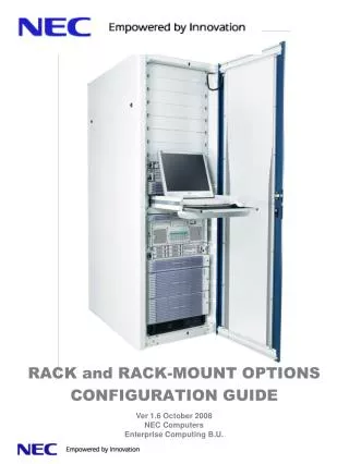
RACK and RACK-MOUNT OPTIONS CONFIGURATION GUIDE
RACK and RACK-MOUNT OPTIONS CONFIGURATION GUIDE. Ver 1.6 October 2008 NEC Computers Enterprise Computing B.U. Purpose of this document is to provide information on NEC Rack frames, options and the way to install them. Related documents and software:

RACK and RACK-MOUNT OPTIONS CONFIGURATION GUIDE
E N D
Presentation Transcript
RACK and RACK-MOUNT OPTIONSCONFIGURATION GUIDE Ver 1.6 October 2008 NEC Computers Enterprise Computing B.U.
Purpose of this document is to provide information on NEC Rack frames, options and the way to install them. Related documents and software: - Rack User guide (delivered with all rack frames) - InRack Wizard software (get latest release on NEC Intranet) - Servers/Storage user guides (It is contained in ExpressBuilder or documentation CDdelivered with each servers and storage device ) • Table of content • 42U RACK FRAME (FIS and NO FIS) FEATURES • 16U RACK FRAME FEATURES • NEC Express Rack-Mount System Assembly • Notes • Frames Options • Display/Keyboard/Mouse Container • KVM (Keyboard Video Mouse) Switches • UPS (Uninterruptible Power Supply) • PDU (Power Distribution Units) • RACK installation rules • RACK power redundancy distribution configurations • PDU connection rules • Rack cooling • Document changes Rack configuration Guide Rev 1.6
42U RACK FRAME (FIS and NO FIS) FEATURES Rack configuration Guide Rev 1.6
16U RACK FRAME FEATURES Rack configuration Guide Rev 1.6
Longer than 450mm NEC Express Rack-Mount System Assembly • To install a NEC Express rack-mount system into a non-NEC rack cabinet, the following requirements must be met. Check the specification of your cabinet or measure your cabinet size before installation. • A standard EIA 19-inch rack cabinet • 2. Perforations are provided for cooling both on the front and rear doors. • (For proper ventilation, NEC Express rack cabinet is provided with perforations of 67% square • holes on rear doors and 78% Honeycomb on front door.) • 3. Vertical mounting rails are provided both on the front and rear sides of your cabinet to • Secure the system. The rails must have the form and hole sizes required as below. • (The rails are often described as “mount angles”.) Front mounting holes (same for the rear side) Vertical mounting rails to secure the system Rack configuration Guide Rev 1.6
Following inner size specification must be respected E Rack configuration Guide Rev 1.6
Notes How to read the block diagram in this document Can be installed Horizontally and/or Vertically In 42U and 42UFIS frames Can be used in 42U FIS Frame Can be used in 42U Frame Can be used in 16U Frame Number of U used Short description Master PDU [ASP-4022-00-00] #1 inlet IEC320/C19 #12 outlet IEC320/C13 Connection line means: it can be connected, used with the other component Can be installed Horizontally In 16U frame Picture Reference [ASP-4022-00-00] in blue available codes [ASP-4022-00-00] in red EOL codes [XXX-XXXX-XX-XX] Not yet introduced product under evaluation Comment: If Warning message read it carefully Rack configuration Guide Rev 1.6
19-inch Rack 16U and 42U Frames Options Front side fillers [AZA-4002-00-00] 1U * [AZA-4003-00-00] 2U * [AZA-4004-00-00] 3U * [AZA-4005-00-00] 6U * To optimize the RACK cooling unused space in front Rack side must be filled with these front side fillers - Each code contains #2 fillers and requested screws/Captive nuts. Front side stabilizer [AZA-4018-00-00] Stabilizer is used to make rack frame structure more stable it must be fixed on the front side of rack frame . lateral front side filler with brush [AZA-4019-00-00] To optimize rack cooling and to allow front side equipment cabling. AZA-4019-00-00 contains 1 lateral front side filler with brush Lateral front side filler [AZA-4020-00-00] To optimize rack cooling lateral rack filler. AZA-4020-00-00 contains 4 rigid lateral front side filler 42U FIS delivered with AZA-4020-00-00 installed Vertical Cable guide [AZA-4022-00-00] Cable guide vertically installable on the back side of 42U rack frames. AZA-4022-00-00 contains 1 Vertical Cable guide 42U FIS delivered with #2 AZA-4022-00-00 installed Rack configuration Guide Rev 1.6
Frame options installation details and usage [AZA-4019-00-00] typical usage LAN switch cables connection Keeping optimum rack cooling [AZA-4022-00-00] [AZA-4019-00-00] Or [AZA-4020-00-00] Indication of U numbering Are stick on the four mounting rails [AZA-4018-00-00] [AZA-4002-00-00] 1U [AZA-4003-00-00] 2U [AZA-4004-00-00] 3U [AZA-4005-00-00] 6U Rack configuration Guide Rev 1.6
M5 Screws, washer s and captive nuts kit [AZA-4017-00-00] Kit containing Qty 20 of each: M5x16 screws, captive nuts and washer s Rack baying kit [AZA-4021-00-00] 42U rack frames baying kit. After removing rack’s lateral side covers, two or more frames can be solidly joined. 1U Universal rail kit [AZA-1100-00-00] Universal fixing rails kit. It can be used to install equipment that are not specifically provided with rack installation rails. Devices installed on xx must be within these maximum specification Width: between 410mm and 450 mm Depth: between 650mm and 900 mm Weight: < 80Kg Rack configuration Guide Rev 1.6
Display/Keyboard/Mouse Container LCD/Keyboard/Mouse Container [NZA-4060-00-00] Container to store a LCD/ keyboard/mouse in a rack cabinet. Keyboard/Mouse Container [AZA-4009-00-00] Container to store keyboard and mouse in a rack cabinet. Mini Keyboard + Mouse PS2 MW [AIP-0020-FF-00] French keyboard [AIP-0020-UU-00] US keyboard [AIP-0020-BB-00] British keyboard Mini keyboard 104 keys + mouse Integrated LCD/Keyboard/Touch Pad + 16 ports KVM tray [CDV-LCDX-02-00] FR keyboard [CDV-LCDX-23-00] US keyboard Integrated LCD, keyboard touch pad in a 1U rack cabinet. Integrating a KVM 16 ports It can be chained to any of following KVM AEX-0800-00-00 /AEX-1610-00-00 andCDV-KVMX-IP-00 to enable Over IP 16P KVM Integrated LCD/Keyboard/Touch Pad tray [AZA-4050-UU-00] US keyboard [AZA-4050-FF-00] FR keyboard [AZA-4070-02-00] FR keyboard [AZA-4070-23-00] US keyboard Integrated LCD, keyboard touch pad in a 1U rack cabinet. It can be connected to any of following KVM AEX-0800-00-00 /AEX-1610-00-00 / AEX-1630-00-00 / AEX-1625-00-00 Generic Support (2U) [AZA-4024-00-00] Replace [AZA-4006-00-00] It can support any device within these max specifications: Width:<=450mm Depth: <=400mm Weight: <=18Kg Rack configuration Guide Rev 1.6
KVM (Keyboard Video Mouse) Switches Server Switch Unit (8 servers/1User) [AEX-0800-00-00] The Server Switch Unit [AEX-0800-00-00] allows up to 8 servers to be controlled by one set of a display, keyboard and mouse. By connecting 9 Server Switch Units in a tree structure, up to 64 servers can be controlled. It can be cascading with AEX-1610-00-00 and/or AEX-0800-00-00 Server Switch Unit (16 servers/1User) [AEX-1610-00-00] The Server Switch Unit [AEX-1610-00-00] allows up to 16 servers to be controlled by one set of a display, keyboard and mouse. By connecting 17 Server Switch Units in a tree structure, up to 256 servers can be controlled. It can be cascading with AEX-1610-00-00 and/or AEX-0800-00-00 Server Switch Unit Over IP (16 servers/1user local or Connection over IP) [AEX-1630-00-00] The Server Switch Unit [AEX-1630-00-00] allows up to 16 servers to be controlled by one set of a display, keyboard and mouse. By connecting nine Server Switch Units in a tree structure, up to 256 servers can be controlled. It can be cascading with with AEX-1610-00-00 and/or AEX-0800-00-00 KVM over Ip enabler [CDV-KVMX-IP-00] The Over Ip enabler Unit is chained to the local KVM AEX-1610-00-00 and/or AEX-0800-00-00 in order to add, in addition to a local video/keyboard/mouse, Over IP functionality USB type interface to CAT5 adapter [ACN-0811-00-00] VGA and USB adapter shipped with 1.5m and 3m CAT5 green cable PS2 type interface to CAT5 adapter [ACN-0810-00-00] VGA and PS2 adapter shipped with 1.5m and 3m CAT5 green cable Rack configuration Guide Rev 1.6
Configuration 1 Direct connection 1 to 8 [AEX-0800-00-00] or 16[AEX-1610-00-00] servers Kvm cat5 green cable 1.5m and 3m cable Server Server Switch Unit AEX-0800-00-00 or AEX-1610-00-00 RICC ACN-0810-00-00 or ACN-0811-00-00 Over IP connection 1 to 16 servers using AEX-1630-00-00 Configuration 2 Server Server Switch Unit LAN AEX-1630-00-00 RICC ACN-0810-00-00 or ACN-0811-00-00 Kvm cat5 green cable 1.5m and 3m cable Configuration 3 Over IP connection extension using xxx-xxxx-xx-xx AEX-1610-00-00 or AEX-0800-00-00 Server Server Switch Unit CDV-KVMX-IP-00 LAN RICC ACN-0810-00-00 or ACN-0811-00-00 Kvm cat5 green cable 1.5m and 3m cable Rack configuration Guide Rev 1.6
Configuration 4 Connecting 1 to 256 servers locally or remotely managed, cascading server Switch Units AEX-0800-00-00 or AEX-1610-00-00 Or AEX-1630-00-00 AEX-0800-00-00 or AEX-1610-00-00 Server Switch Unit (Master) Server Server Switch Unit (Slave) Up to eight or sixteen servers installable Server Up to eight or sixteen servers installable LAN ACN-0810-00-00 Server ACN-0810-00-00 or ACN-0811-00-00 Over Ip connection only if master KVM is AEX-1630-00-00 Rack configuration Guide Rev 1.6
Configuration 5 Connecting up to 256 servers locally or remotely managed, cascading server Switch Units AEX-0800-00-00 or AEX-1610-00-00 AEX-0800-00-00 or AEX-1610-00-00 Server Switch Unit (Master) Server Server Switch Unit (Slave) Up to eight or sixteen servers installable Server Up to eight or sixteen servers installable CDV-KVMX-IP-00 LAN ACN-0810-00-00 Server ACN-0810-00-00 or ACN-0811-00-00 Rack configuration Guide Rev 1.6
Server Switch Unit (16 servers/2User) [AEX-1625-00-00] The Server Switch Unit [AEX-1625-00-00] allows the control of 16 servers with two set of a display, keyboard and mouse. By connecting 17 Server Switch Units in a tree structure, up to 256 servers can be controlled. USB type interface to CAT5 adapter [ACN-0821-00-00] VGA and USB adapter shipped with 3m CAT5 green cable PS2 type interface to CAT5 adapter [ACN-0820-00-00] VGA and PS2 adapter shipped with 3m CAT5 green cable Configuration 1 Direct connection 1 to 16 servers up to 2 users Server Kvm cat5 green cable 1.5m and 3m cable Up to sixteen servers installable User A AVRIQ ACN-0820-00-00 or ACN-0821-00-00 Server Switch Unit AEX-1625-00-00 User B Rack configuration Guide Rev 1.6
Configuration 3 Connecting 1 to 256 servers locally or remotely managed, cascading server Switch Units User A AEX-1625-00-00 Server Server Switch Unit (Slave) Server Switch Unit (Master) Up to sixteen servers installable Cable ACN-0114-00-00 Server User B Up to sixteen servers installable Server AVRIQ ACN-0820-00-00 or ACN-0821-00-00 Important KVMrules • 1) ACN-0820-00-00 and ACN-0821-00-00 can only be used with AEX-1625-00-00 • do not use them with ACN-0800-00-00 or ACN-1610-00-00 or ACN-1630-00-00 • 2) AEX-1625-00-00 can only be chained with same model AEX-1625-00-00. Do not chain it with ACN-0800-00-00 or ACN-1610-00-00 or ACN-1630-00-00 • 3) Only one level of chaining are supported for all base KVM ACN-0800-00-00 • ACN-1610-00-00 ACN-1630-00-00 and AEX-1625-00-00 • 4) In order to avoid mixing LAN and KVM cables, use specific green cable for KVM connection and grey cables for LAN. Mixing LAN and KVM connection can put out of order your equipment ! Rack configuration Guide Rev 1.6
UPS (Uninterruptible Power Supply) APC SUA1500RMI2U [ABA-1520-00-00] 1500 VA / 980 Watts #1 inlet IEC320/C14 #4 outlets IEC320/C13 #1 Smart Slot Serial/USB Management APC SUA3000RMI2U[ABA-3020-00-00] 3000 VA / 2700 Watts #1 inlet IEC320/C20 #8 outlets IEC320/C13 #1 outlet IEC320/C19 #1 Smart Slot Serial/USB Management UPS Cable latch [ASP-0007-00-00] #1 inlet IEC60309 #1 outlet cable APC SURTD5000RMXLI [ABA-5010-00-00] #1 terminal input block #8 outlets IEC320/C13 #2 outlet IEC320/C19 #2 Smart Slot Serial Management UPS cable latch [ASP-0005-00-00] #1 inlet IEC60309 #1 outlet cable [ASP-0006-00-00] #1 inlet IEC320/C19 #1 outlet IEC60309 Rack configuration Guide Rev 1.6
UPS network card [AEX-2031-00-00] Smart UPS network management card UPS serial card [AEX-2200-00-00] Smart UPS #2 additional serial ports interface UPS 8 port expander [AEX-2008-00-00] 8-Port Share-UPS Interface Expander UPS Configurations 1 Connecting 1 server to UPS with serial connection serial cable [ACN-2000-00-00] Power cable UPS Epress5800 Server [ABA-1520-00-00] [ABA-3020-00-00] [ABA-5010-00-00] Epress5800 Server [ACN-2000-00-00] serial cable Epress5800 Servers Power cable UPS [ABA-1520-00-00] [ABA-3020-00-00] [ABA-5010-00-00] + [ABA-5010-00-00] Rack configuration Guide Rev 1.6
UPS Configurations 2 AEX-2008-00-00 8-Port Share-UPS serial serial Interface Expander serial cable serial cable Server Up to eight servers installable UPS Power cable [ABA-1520-00-00] [ABA-3020-00-00] [ABA-5010-00-00] Following table show the estimated autonomy of devices connected to a UPS. - Define max load connected to UPS in Watt or VA and find the autonomy in Hours:Minutes Rack configuration Guide Rev 1.6
PDU (Power Distribution Units) Master PDU [ASP-0020-00-00] #1 inlet IEC60309 (32A no protection) #8 outlet IEC320/C13(x4 10A circuit breaker) #2 outlet IEC320/C19(x2 16A circuit breaker) Slave PDU [ASP-0022-00-00] #1 inlet IEC320/C19 (16A no protection) #12 outlet IEC320/C13(x2 10A circuit breaker) #1outlet IEC320/C20(no protection) Slave PDU [ASP-0021-00-00] #1 inlet IEC320/C14 (10A fuse protection) #8 outlet IEC320/C13(no protection) IEC320 Power cord [ACN-2001-00-00] 3 m power cord with one C13 and one C14 plug Rack configuration Guide Rev 1.6
PDU (Power Distribution Units) Master PDU [ENS-12C1-32-01] #1 inlet IEC60309 (32A no protection) #12 outlet IEC320/C13(x4 10A circuit breaker) - No output cables included !!! Master PDU [ENS-2C13-32-01] #1 inlet IEC60309 (32A no protection) #2 outlet IEC320/C13(x2 10A circuit breaker) #4 outlet IEC320/C19(x4 16A circuit breaker) - No output cables included !!! Master PDU [ENS-8C13-32-01] #1 inlet IEC60309 (32A no protection) #8 outlet IEC320/C13(x4 10A circuit breaker) #2 outlet IEC320/C19(x2 16A circuit breaker) - No output cables included !!! Master PDU [ENS-6C19-32-01] #1 inlet IEC60309 (3x32A no protection) #6 outlet IEC320/C19(x6 16A circuit breaker) - No output cables included !!! 3 Phases input needed ! IEC320 Power cord [ACN-2001-00-00] 3 m power cord with C13/C14 plugs IEC320 Power cord [ACN-2002-00-00] 2 m power cord with one C19 and one C20 plug Rack configuration Guide Rev 1.6
PDU (Power Distribution Units) Slave PDU [ENS-12C1-16-01] #1 inlet IEC320/C19 (16A no protection) #12 outlet IEC320/C13(x4 10A circuit breaker) - Include one input cable ACN-2002-00-00 - No output cables included !!! Slave PDU [ENS-6C13-16-01] #1 inlet IEC320/C14 (10A no protection) #4 outlet IEC320/C13(x2 10A circuit breaker) - Include one input cableACN-2001-00-00 - No output cables included !!! IEC320 Power cord [ACN-2001-00-00] 3 m power cord with one C13 and one C14 plug Rack configuration Guide Rev 1.6
10A CB ENS-6C13-16-01 10A CB 10A CB 10A CB ENS-12C1-16-01 10A CB 10A CB 10A CB 10A CB 10A CB 10A CB 10A CB 16A CB 16A CB 16A CB 16A CB 16A CB 16A CB 10A CB 10A CB 10A CB 10A CB 10A CB 10A CB 10A CB 10A CB 10A CB 16A CB 16A CB 16A CB 16A CB 16A CB 16A CB PDUs blocks diagram Master PDUs ENS-12C1-32-01 ENS-2C13-32-01 ENS-8C13-32-01 ENS-6C19-32-01 Slave PDUs Rack configuration Guide Rev 1.6
Devices power specifications 1-3 Max WATT = Maximum power consumption for full configuration in watt Max Curr. = Maximum current required Max BTU = Maximum BTU dissipated by equipment at maximum power consumption Inlet Nb NR = Number of inlet plugs for non redundant configuration Inlet Nb R = Number of inlet plugs for non redundant configuration Inlet type = inlet plug type Power supply side = Looking from the back of the device where the PSU are placed Right Left Center Cable-Arm / Cable Length = minimum cable length W or W/O cable arm to connect the device Rack configuration Guide Rev 1.6
Devices power specifications 2-3 Rack configuration Guide Rev 1.6
Devices power specifications 3-3 Rack configuration Guide Rev 1.6
Tec Notes RACK installation rules 42 U frames C D B 16 U frame B C A D A Use last available release of InRack Wizard software for RACK configuration Rack configuration Guide Rev 1.6
Tec Notes Exp5800 server 42U RACK installation rules NEC D >=125cm front front Dis the minimum rack clearance betweentwo 42U frames to allow easy maintenance Minimum clearance around a 42U frames Rack configuration Guide Rev 1.6
Tec Notes Exp5800 server 16U RACK installation rules NEC D >=125cm front front Dis the minimum rack clearance betweentwo 16U frames to allow easy maintenance Minimum clearance around a 16U frames Rack configuration Guide Rev 1.6
Express5800 Server Express5800 Server Express5800 Server Express5800 Server Express5800 Server Express5800 Server PSU PSU PSU PSU PSU PSU PSU PSU PSU PSU PSU PSU Tec Notes PSU PSU PSU PSU PSU PSU PSU PSU Fig. 2 Fig. 3 Fig. 1 Express5800 Server PDU PDU PSU PDU Express5800 Server PSU PDU PDU PDU Express5800 Server PSU Master PDU Master PDU UPS Epress5800 Server Epress5800 Server Epress5800 Server Powersource Powersource Power source Fig. 4 PDU PDU Epress5800 Server PSU PSU Epress5800 Server PDU PDU PSU PSU Epress5800 Server UPS Power source RACK power redundancy distribution configurations In following power distribution diagrams, five different ways to configure interconnection of Master PDU, Slave PDU, UPS and servers power redundancy. In red components that represent a single point of failure (SPOF). Failure on red components will induce a power failure on all components cascaded. Configuration 5 is the one completely redundant, configuration 1 has no redundancy. Fig. 5 PDU PDU PDU PDU UPS or Master PDU UPS or Master PDU Power source (UPS) Power source (MPDU) Power source (UPS) Power source (MPDU) Rack configuration Guide Rev 1.6
Tec Notes PDU connection rules L1 Imax 11A C13 Do not exceed maximum current allowed for group of plugs. ASP-0020-00-00 has 4 groups of two C14 plugs protected by a 10A circuit breaker L2 Imax + L3 Imax > 10A C14 C13 Do not exceed MAX current allowed for the single defined plug. Imax current for IEC320-C13/C14 is 10A L1 Imax > 10A L2 Imax 6A C14 C13 C14 C13 L3 Imax 7A C13 C14 C13 C14 C14 L4 Imax 9A C13 C14 C13 L5 Imax 12A C19 C14 C20 C19 L6 Imax 15A C19 Do not exceed MAX PDU input current. ASP-0020-00-00 has one IEC60309 input plug with maximum current of 32A. Protection by over current must be guarantee by the upfront device where this PDU is connected. L4 Imax + L5 Imax + L6 Imax > 32A C20 C19 ASP-0020-00-00 31A 60309 Rack configuration Guide Rev 1.6
Tec Notes PDU selection and sizing rules 1st - List all your devices you want to install inside the rack frame - using the “devices power specifications” pag. 16-17 define the maximum current and plug type for each device 2nd - Using PDU specification identify the maximum current per groups of outputs example: ASP-0022-00-00 has two groups of six C13 plugs. Each group is protected by 10A circuit breakers. 3rd - Adding all PDU output currents you should not exceed max input current allowed by PDU example: ASP-0020-00-00 has an IEC60309 input plug limited to 32A 4rd - Select your power distribution model between the ones listed on page 21 Imax 6A C13 C14 C13 Imax 4A C14 C13 C13 C14 C13 C14 Imax 3A C13 C14 C13 S devices I Max <= 10A C14 C14 Imax 1A C14 C13 C13 C14 C14 C14 Imax 1A C13 S devices I Max x group <= 10A C14 C14 C14 S devices I Max <= 10A S devices I Max <= 16A C14 C13 C14 S devices I Max <= 32A Imax 4A C14 C13 C14 C14 C14 C14 C14 S devices I Max <= 16A S devices I Max <= 10A C14 C13 C14 C14 C14 C14 15A C20 C19 C14 C14 S devices I Max x group <= 16A S devices I Max <= 10A C13 10A C20 C19 C14 C20 C19 C14 Imax 2x6A ASP-0020-00-00 C13 C13 ASP-0022-00-00 C14 31A 60309 C20 C19 ASP-0022-00-00 Rack configuration Guide Rev 1.6 Example of interconnection of one Master PDU ASP-0020-00-00 and two slaves ASP-0022-00-00 with different load devices
Tec Notes Rack frame front rear Rack cooling Front and lateral cover usage Rack cooling air flow Air cooling flow is always going from the front to the back of the rack frame With out the front side panels and laterals Covers exhausted warm air will be xxx from the front side Example of Rack assembly Using front and lateral covers Pictures showing temperatures inside the rack with and with out the side/front panels Rack configuration Guide Rev 1.6
Tec Notes Building ceiling Grilles Grilles Grilles Suspended ceiling Air Conditioner Rack Rack Rack Rack Rear Rear Front Front Front Front Rear Rear Raised floor Grilles Grilles Building floor Rack cooling Rack organization in a datacenter with raised floor and suspended ceiling with air-conditioner Rack configuration Guide Rev 1.6
Tec Notes Rack cooling CFM The abbreviation for cubic feet per minute. CFM is used to measure the flow of air through a delivery system or space. BTU The abbreviation for British Thermal Unit. A measurement of heat energy commonly used to measure heat loads in data centers and IT rooms in North America. A BTU is defined as the amount of heat energy required to raise the temperature of one pound of water by one degree Fahrenheit in one hour. This unit should be replaced by Watt Watt A measurement of energy commonly used to measure electrical and heat loads in data centers and IT rooms. The wattage consumed by the IT equipment, lights, etc. is the amount of heat energy to be removed from the room by the air conditioning system. This term is becoming more common when specifying cooling systems. Relative Humidity The amount of water vapor contained in air relative to the maximum amount the air is capable of holding. Expressed in %. Ton (Cooling) A measurement of heat energy commonly used historically to measure heat loads in data centers and IT rooms in North America. A ton is equal to 12,000 BTUs and is the amount of heat energy required to melt 2000 pounds (907kg) of ice in one day (24 hours). This is an archaic term typically used to specify heat output when expressed in Tons / day, where the use of the more modern term Watts is the simpler and more universal measure that should be used. Rack configuration Guide Rev 1.6
Tec Notes English to Metric Conversion table Some of the most commonly used unit Very useful free ware program to convert any units can be downloaded at this link http://joshmadison.com/article/convert-for-windows/ Rack configuration Guide Rev 1.6
Document change history Rack configuration Guide Rev 1.6