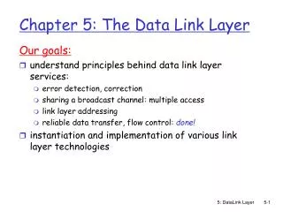
Insertable B-Layer Status & Plans
Insertable B-Layer Status & Plans. ATLAS Inner Detector General Meeting CERN, 28 November 2008 G. Darbo - INFN / Genova Workshop page: http://indico.cern.ch/conferenceDisplay.py?confId=22937. From Replacement to Insertable BL. One ye ar ago (29/9/2007) the B-Layer Replacement Workshop

Insertable B-Layer Status & Plans
E N D
Presentation Transcript
Insertable B-Layer Status & Plans ATLAS Inner Detector General Meeting CERN, 28 November 2008 G. Darbo - INFN / Genova Workshop page: http://indico.cern.ch/conferenceDisplay.py?confId=22937
From Replacement to Insertable BL • One year ago (29/9/2007) the B-Layer Replacement Workshop • Serious difficulties found in the original idea of replacement • Longer than foreseen shutdown of LHC for replacement (>1 year) • Activation of present detector -> safety issues • Need to dismount SQP, disks, etc to access B-Layer -> time, risk of damage • ATLAS appointed a BL Task Force (A.Clark & G. Mornacchi) which reported in Bern, final report under evaluation at EB. • BLTF findings and recommendations: • Current B-layer will not survive until end of Phase I (Radiation damage, lost hits at high rate) • Cannot replace in even the extended winter shutdown foreseen for end 2012 (Replace means remove pixel package with beam-pipe, open up in SR1, remove old B-layer and its services, put in new one with services, re- integrate to beam-pipe and re-install in ATLAS) • Many recommendations, main thrust is we should opt for insertion of a new b-layer (IBL), inside the current pixel detector, leaving the current b-layer in place.
LHCC: Integrated Luminosity • Integrated luminosity affects detector life – Peak Luminosity affects R/O INTEGRATED LUMINOSITY Integrated Luminosity: 2008-17: 650 fb-1 2013-17: 550 fb-1 New injectors + IR upgrade phase 2 Long Shutdown (8 months) Peak Luminosity: 2017: 3x1034 cm-2s-1 SLHC Start-up Early operation Collimation phase 2 Linac4 + IR upgrade phase 1 Ref: LHCC 1/7/2008 – Roland Garoby
B-Layer Scenarios To maintain Pixel Detector performance with inserted layer, material budget is critical. Development of new local support structure with carbon-carbon foams. WH(120 Gev) SV1 εb=60% Light jets rejection SV1 εb=70% 2-layers R=3.5 cm and 8 cm 2-old layers ATLAS b-inserted as 4-layer R=3.5 cm b-replaced
B-Layer Replacement - Insertion Smaller radius B-layer to insert in the existing Pixel • 16-staves (present module “active” footprint gives hermetic coverage in phi) not shingled b-layer. Requires new smaller beam-pipe; • Pixel Modules: increase live area of the footprint: • New chip design (FE-I4) – live fraction, I/O bandwidth, 200 Mrad; • Sensor – increase radiation hard (smaller radius and ramping up LHC luminosity):3x10¹⁵ neq/cm2. New radiation dose simulation is going on with new releaso of Fluka. R&D and prototyping in 2009, construction 2010-2012;
Critical Issues – Available Envelopes • Nominal Current B-Layer inner radius is just over 46 mm. • Envelope for B-Layer is 45.5 mm. • Assumed that is possible to reduce the beam pipe envelope • Reduce beam pipe isolation • Smaller beam pipe? R=25mm? • Need also clearance for beam pipe alignment (together with IBL) Present envelopes
Possible Layouts • With “agreed” FE-I4 size full coverage • Fighting for space to old blayer fights against full coverage • 15 staves looks the most promising, at 35 (not shown) or 36 mm radius, but mechanically is tight • We may not profit from smaller radius beampipe so much if we want full coverage (with this module size) • Retune FE-I4 size? Curved (min R=1m) straight 7mm offset Radius (mm) = 38 37 36 Tilt (deg) = 17 16 15 No. of staves = 16 15 15 Coverage Diagram
Frontend Chip - FE-I4 20.2mm 7.6mm FE-I3 @ R=5cm ~200μm • Reasons for a new FE design: • Increase live fraction • New architecture to reduce inefficiencies (L=3xLHC) • New FE-I4 • Pixel size = 250 x 50 µm2 • Pixels = 80 x 336 • Technology = 0.13µm • Power = 0.5 W/cm2 16.8mm ~19 mm active IBM reticule 8mm active 3xLHC sLHC 2.8mm ~2mm Chartered reticule (24 x 32) FE-I3 74% FE-I4 ~89% LHC inefficiency Hit prob. / DC
FE-I4 Architecture: Obvious Solution to Bottleneck • >99% or hits will not leave the chip (not triggered) • So don’t move them around inside the chip! (this will also save digital power!) • This requires local storage and processing in the pixel array • Possible with smaller feature size technology (130nm) Local Buffers pixels pixels Column pair bus Data transfer clocked at 20MHz bottleneck Sense amplifiers Buffer & serialiser Serial out trigger End of columnbuffer 64 deep trigger FE-I3 Column pair FE-I4 Column pair
FE-I4_proto1 collaboration • Participating institutes: Bonn, CPPM, Genova, LBNL, Nikhef. Bonn: D. Arutinov, M.Barbero, T. Hemperek, M. Karagounis. CPPM: D. Fougeron, M. Menouni. Genova: R. Beccherle, G. Darbo. LBNL: R. Ely, M. Garcia-Sciveres, D. Gnani, A. Mekkaoui. Nikhef: R. Kluit, J.D. Schipper FE-I4-P1 3mm LDORegulator 61x14 array Control Block ChargePump CapacitanceMeasurement SEU test IC 4mm DACs CurrentReference ShuLDO+trist LVDS/LDO/10b-DAC 4-LVDS Rx/Tx
Modules & Stave Arrangement • Two module options: • Single chip modules abut one against the next • Small sensor type: like 3D, active edge • Multi chip modules: chip look the same if using multi-chip modules • As present sensor size (~3xFE-I4) : like planar n-on-n • assuming no Z-shingling, no space. W-bond pads
Sensors Options Planar (n-on-n) Pro’s n-on-n is a proven technology Lower Cdet -> lower noise, lower in-time threshold for same power settings in the FE. Partially depleted sensors collect charge Con’s No active edge (?) Guard ring -> dead area in Z, constraints the envelope (?) Charge collected at 600Vbias • Two “silicon” technologies considered: Planar and 3D sensors. • Could profit from 2 large “SLHC” R&D communities. 3D sensor • pro’s: • Larger charge collection after irradiation (but more power in the FE for same time-walk) • Active edge (butting modules) • Lower voltage (<150 V), power after irradiation • Con’s: • column Inefficiency, need tilt sensors. • Higher Cdet • No experience in “scale” production • Several options and design flavours • Higher cost. Yield? • Other options? Diamonds could be a compatible technology • No cooling issues, low capacitance, no leakage current make them appealing… • Smaller community than silicon…
Internal Services – Stave Cable • Stave cable still on conceptual stage: • Cable using System Task force recommended signals + direct power. • Wire bonding MUST be done on stave • Many ideas (none developed to the end) • Single cable (conceptually like a circuit board to connect the FE chips) • Monolithic cable on top or on the bottom • Single cable also possible • Space is limited, what about reworking? End-of-stave connectors Unfolded cable Monolithic Cable on the Bottom
From End-of-Stave (EOS) to PP1 3650 mm “Strawman” Issuess: • X-section of LV cables • No active EOS -> 4m (FE-I4 to PP1) • Connector space. • Fitting connectors in place at PP1 …more work to come to a design -
External Services – ID Endplate • Final services arrangement necessitated improvisation • Cable over-length, mapping changes. Not all improvisations are documented in situ cross check has to be done before next yeay closing of ATLAS. • Entering of nose region is critical even for few additional services, as available envelope is basically taken
External Services • Installation of additional services for IBL is certainly not straight forward • Careful design on flange (and in ID endplate region) is necessary, which must combine • Verification in situ • New design/drawings (in CATIA for flange) • Pipe routing for eventual CO2 cooling up to USA 15 should be o.k. • Radiation protection aspects have to be considered early enough All installation aspects of new IBL services have to be considered from the very beginning !
Cooling – CO2 vs C3F8 • IBL cooling parameters: • 15 staves with 112W each → Ptotal =1.68kW • Tsensor -25°C, ΔT to coolant ≤10°C → Tcoolant -35°C • Options (limited by main constraint: develop time & working experience): • CO2: copy of the LHCb VELO system, similar in cooling power. • FC: present C3F8 system (after modifications). • Consider the new ATLAS and CERN reorganisation of the Cooling group: • ATLAS long term Upgrade and the improvement of present C3F8 system • Available Nikhef interest in contributing in the CO2 system (“cooling guru”).
LHCb-VELO Cooling System 2PACL (2-Phase Accumulator Controlled Loop) principle of cooling: • Liquid overflow => no mass flow control • Low vapor quality => good heat transfer • No local evaporator control, evaporator is passive in detector • Very stable evaporator temperature control with 2-phase accumulator (P4-5 = P7) Long distance P4-5 P7 5 Heat out Heat out Condenser 6 Heat in 4 Heat in 2 3 evaporator Restrictor Heat exchanger 1 2-Phase Accumulator Pump Vapor Liquid Pressure 2 3 2-phase 4 P7 5 1 6 Enthalpy Enthalpy
R/O Links • Changes (strawman R/O from System Task force): • Down link (TTC) stay the same 40Mb/s (Manchester coding) – to 2 FE-I4 (?) – need clock multiplier in the FE-I4 (issues of SEU for clock multiplier). • Uplink use 160 Mb/s data+clock (8b/10b encode) – Single FE-I4 • Need new BOC design (substitute custom ASIC(s) with FPGA) • ROD could stay the same: reprogram FPGA (or new design for x2 links: need also 2 S-Links) • Use GRIN fibers (under rad-test for SLHC, or new Ericsson) • Opto-board at PP1 – need test of reliable electrical signal transmission (~4m) Present system
Powering and DCS • Power scheme – Independent powering with PP1 regulators: • Use, on FE-I4 chip, x2 DC/DC and/or LDO conversion • DCS: similar implementation that today • Temperature sensors not on each module, smaller granularity • More than 600V if planar sensors? • Minor changes needed but it has a lot of different components to build/acquire. PP2 regulator 2.5V LDO 3.3V DC/DC FE-I4 Chip (the same we have now) Remote sensing not needed for LDO (?) at PP1 for DC/DC
IBL Project Organization • IBL Coordinator reporting to ATLAS and Pixel community (PL and Institute Board) • Expected to come from present Pixels • Selection process and appointment should be completed for Feb’09 Collaboration Board • Documents • WBS in preparation • TDR in 2010. (in discussion if a TP is needed in late 2009) • Funding Model • The overall model for the B-Layer Replacement was that this part of the detector was a “consumable”. • A dedicated line of funding, contained inside the Pixel M&O B, exists for the B-Layer Replacement: for 2009 - 2012 construction period is foreseen to be roughly 4 MCHF. • The Project Office funding is foreseen to come largely from M&O A. • First, very rough, cost estimates would indicate a cost of about 7-8 MCHF, including the new beampipe.
Conclusions • Big progress in convergence to a B-Layer project: IBL • Feasibility studies on-going and “strawman” coming soon for several subparts • Organization structure in discussion • Cost evaluation and funding model • Interest from groups to contribute. Open to Pixel and ATLAS • Challenging project • It will be an “assurance” for present B-Layer both for radiation end-of-life and for hard failures • Time scale is short, need optimization of design and prototyping but no time for basic R&D • Options should be kept small: decision between option is usually long and require parallel efforts.