Download
1 / 22
240 likes | 386 Vues
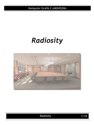
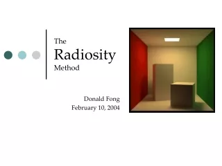
Radiosity. Jian Huang, CS594, Fall 2002 This set of slides reference the text book and slides used at Ohio State. Radiosity. Radiosity is a global illumination model that assumes all surfaces are diffuse and computes view independent illumination.

E N D
Radiosity Jian Huang, CS594, Fall 2002 This set of slides reference the text book and slides used at Ohio State.
Radiosity • Radiosity is a global illumination model that • assumes all surfaces are diffuse and computes view independent illumination. • Radiosity computes the intensity reflected from each small surface region ( differential area ) equally in all directions (including the eye...). This intensity includes energy emitted by the surface itself and reflected energy from other objects. • Following an (expensive) preprocessing to compute radiosity, the model is shaded and can be rendered interactively.
Basic Definitions • Radiosity: (B) Energy per unit area per unit time. • Emission: (E) Energy per unit area per unit time that the surface emits itself (e. g., light source). • Reflectivity: (r) The fraction of light which is reflected from a surface. (0 <= r <=1) • Form- Factor: (F) The fraction of the light leaving one surface which arrives to another. (0<=F<=1)
The Basic Radiosity Equation • We will compute the light emitted from a single differential surface area dAi. • It consists of: • 1. Light emitted by dAi. • 2. Light reflected by dAi. • depends on light emitted by other dAj, fraction of it reaches dAi. • The fraction depends on the geometric relationship between dAi anddAj: the formfactor .
The Basic Radiosity Equation • The relationship between a single differential area’s radiosity and the radiosities of the rest of the environment:
The Discrete Radiosity Equation • We can’t operate in continuous space. We need a finite problem! • We divide the surfaces into small discrete areas called patches. We assume that radiosity and emission do no vary across the patch area. • The radiosity of a patch is then: • Or, more conveniently:
The Reciprocity Relationship • If we had equal sized emitters and receivers, the fraction of energy emitted by one and received by the other would be identical to the fraction of energy going the other way. • Thus, the formfactors from Ai to Aj and from Aj to Ai are related by the ratios of their areas: • Thus: • The radiosity equation is now:
Matrix Formulation • For an environment of N patches: • Because the sum of formfactor along a lines is less then 1, this matrix is diagonally dominant and therefore iterative Gauss- Siedel is guaranteed to (quickly) converge to a solution!
The Formfactor • The formfactor is purely a function of geometric relationship between patches and thus does not depend on viewer position or surface reflectivity attributes. • Between differential areas:
Computation Hurdles • Computation of the formfactors • Solutions: hemicube, elements. • Solution of the matrix in time O(N2). • Solution: progressive shooting.
Nusselt’s Analog • The inner integral in the previous double integral represents the formfactor from a differential area to a finite patch. This quantity can also be computed by the fraction of the base of the hemisphere covered by the projection:
The Hemi-cube • Any patch which covers the same projected area on the hemisphere has the same formfactor. • Any surface can be used to project the patches onto, without changing the formfactor.
The Hemi-cube • Compute the delta formfactor of each grid cells DF and store in a table (next slide...). • Project all patches onto the ‘ hemi- cube ’ screen (use Z- buffer rendering hardware?), drawing a patch- id instead of color. • Sum the delta form factors of all grid cells covered by the patch’s id.
Problems with the Hemi-cube • Because we compute only the inner integral serious inaccuracies can occur if the size of the patch is large relative to the distance. • Because the hemisphere is divided into discrete solid angles, a number of aliasing problems may occur.
Patches and Elements • Patches are used for emitting light. Some patches are divided into elements, which are used to more accurately compute the received light after the patch solution have been computed.
Progressive Radiosity • The problem: we need to solve a set of N equations – O(N2) time. • In the conventional radiosity we gather the contribution of other patches to patch i.
Shooting Radiosity • Shoot the radiosity of patch i and update the radiosity of all other patches.
Visual Comparison • Assume the scene is displayed after each update: • In the ‘row solution’ (gather), every image will show another element being fully illuminated. • In the ‘column solution’ (shoot), every image will show the whole image change due to the contribution by one element. The magnitude of this change depends on the amount of energy BiAi sent out from the ‘shooting’ patch. • Therefore, the image will converge faster to the final solution if the patches with highest added energy DBiAi shoot first!
Comparing Radiosity and Ray-tracing • Radiosity: • Object space • Only diffuse (specular is too expensive to do, why?) • View independent • Ray-tracing: • Image space • Only specular (why?) • View dependent • Which is more realistic? • Are we stuck on techniques towards realism? • Distributed Ray Tracing and Photon mapping!!
More Issues... • Specular illumination • Reflections (ray tracing) • Participating media • Adaptive subdivision • Dynamic models • View dependent radiosity • ...