Download
1 / 16
170 likes | 350 Vues
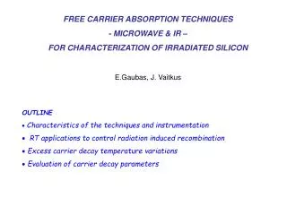
FREE CARRIER ABSORPTION TECHNIQUES - MICROWAVE & IR – FOR C HARACTERIZATION OF IRRADIATED SILICON. E.Gaubas, J. Vaitkus. OUTLINE Characteristics of the techniques and instrumentation RT applications to control radiation induced recombination

E N D
FREE CARRIER ABSORPTION TECHNIQUES - MICROWAVE & IR – FOR CHARACTERIZATION OF IRRADIATED SILICON E.Gaubas, J. Vaitkus • OUTLINE • Characteristics of the techniques and instrumentation • RT applications to control radiation induced recombination • Excess carrier decay temperature variations • Evaluation of carrier decay parameters
Carrier recombination and trapping ☼Recombination (fast) and trapping (slow) constituents within transients of microwave absorption by free carriers (MWA) can be distinguished by combining analyses of the excess carrier decays dependent on the excitation intensity and bias illumination (BI). RT Transients at different temperatures electrons-irradiated Si protons-irradiated Si Variation of MWA decays with excitation intensity (proportional to the initial amplitude) with and without additional cw illumination
E IR, MW cw probe k laser light pulsed excitation R Characteristics of the MW & IR techniques and instrumentation Principle of the transient techniques Density of free carriers is controlled IRA =(4/c)dc {/[1+(sc )2]} 2 MWA >100m 0 =(4/c )dc, < 0 Transient: (t) (t) FCnexFC (t)
Advantages: ☼ direct control of carrier decay process: - to separate impact of different recombination and trapping mechanisms, - to determine type of defects ( ~F(nex/ndop)), parameters of traps ( ~F(T)), etc. - to reveal complicated systems of defects, barriers, non-linear decay processes etc, ☼ contact-less and fast measurement procedure, ☼ non-destructive and distant measurementtechniques: IR (tens of cm), MW (from tens of m to tens of mm), ☼ wide range of lifetime variations ( 1 ns (NR 102) – 10 ms (NR 10-5), RT), ☼relatively high spatial resolution (from tens of m to tens of mm integration area), ☼ wide range of injection levels (nex/ndop from 0.01 to 100 - for MW. and 1- 103 for- IR).
Limitations: ☼ optically polished surfaces and relatively high excitation levels (nex 1016 cm-3) for IR, ☼ metallised areas are un-acceptable for examination, ☼ MW probing depth depends on material resistivity (decreases with resistivity), ☼ resolution of very short lifetimes ( <1 ns) is limited by oscilloscopic instrumentation and detector (MW / IR) circuits, ☼ examination of thin layered structures is complicated
Microchip laser STA-01 exc ~700ps, Eexc 10 J Attenuator of light density Sliding short sample MW slit antenna Sliding short MW bridge M M B B tiltas tiltas Sliding short MW oscillator with adjustable power and frequency M MW circulator B cir k ulator ius ³ ³ f f 0.5 0.5 GHz, GHz, £ £ U U 1 mV/pd 1 mV/pd MW detector Rload Amplifier (>50) TDS-5104 Coaxial needle-tip MW antenna Fiber excitation - - x z Laser-fiber beam d Si Ge Analyser of the recombination parameters Main instrument Supplementary regimes Lifetime-temperature variations Lifetime depth-scans
Coaxial needle-tip MW antenna laser beam - - z x Si or or Si d Si orGe Ge Laser beam z MW techniques for: - estimation of carrier transport parameters ☼Parallel MWR ☼Oblique MWR ☼ Perpendicular MWR Si or D 67 cm2/s p-Ge D 21 cm2/s p-Si 60 m
N|~10-14 =81010 cm-3 N|~10-16 =1017 cm-3 RT applications to control radiation induced recombination Calibrated RT lifetime variations with fluence for definite particles, exploited for the same material and structures, would enable one to control the densityof theradiation induced dominant traps Proton irradiation Lateral lifetime variation due to irradiation geometry with proton beam spot of 25 mm. - not covered the range of moderate and the highest fluences, - samples from different material (sources) exploited
Neutron irradiation - too small set of samples examined
- rays irradiation (BNL-Helsinki samples) for n-Si a non-linear dependence can be implied 1/R = 1/* + vthN = 1/* + vth(N0 + D), * - carrier capture lifetime attributed to the intrinsic centers; N0–concentration of radiation defects at low dose; D – irradiationdose; = 5.7 108 1/Mrad[Z Li]; > 410-19 cm2
DLTS 0.17 eV DLTS 0.24 eV DLTS 0.42 eV DLTS DLTS Excess carrier decay temperature variations e-irradiated FZ Si -irradiated MCZ Si
Excess carrier decay temperature variations MWR proton-irradiated Si
Generation lifetime Electron capture lifetime Trapping center, e << h Recombination center, e h Hole thermal release lifetime Hole capture lifetime Hole capture lifetime Generation lifetime Recombination lifetime Trapping lifetime Evaluation of carrier decay (trap) parameters • Separation of traps from the transient decay shape and variation with external factors; • Estimation of the parameters for adominant recombination center: • NR 1/vth,Tminority from absolute values of minority if S-R-H approximation holds, • estimation of the ratio e/h from the dependency on excitation level, • evaluation of ER from -Tslope if no additional traps compete; • Detection limitations: ex<< R; simple system of the dominating traps; for radiation defects (NRD>NR, intrinsic) • 3) Evaluation of the parameters of trapping centers from temperature peaks/slopes in -T dependence • (variations of the trapping caused -T as usually prevails in T<TRT, when density of trapping centers is high enough)
Precise simulation of the temperature dependent lifetime variations correlating with DLTS peaks – J.Vaitkus’ method Multi-trapping process Single act of capture/thermal release V2=/- V2-/o V-O MWR decay as peak Common DLTS peaks
Summary ☼ Calibrated RT lifetime variations with fluence for definite particles, exploited for the same material and structures, wouldenable one to control radiation induced density of the dominant traps. However, calibration curves are not determined. ☼ Tentative examination of recombination characteristics dependent on fluence and particle species, by MWR using (T), Iexc, exc, BI are carried out; as(T) variations are correlated with those determined by DLTS technique in the range of relatively low fluences. Thank You for attention!