Computer Design and Organization
410 likes | 444 Vues
Computer Design and Organization. Architecture = Design + Organization + Performance Architecture of modern computer systems Central processing unit : pipelined, exhibiting instruction level parallelism, and allowing speculation .

Computer Design and Organization
E N D
Presentation Transcript
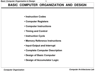
Computer Design and Organization • Architecture = Design + Organization + Performance • Architecture of modern computer systems • Central processing unit: pipelined, exhibiting instruction level parallelism, and allowing speculation . • Memory hierarchy: multi-level cache hierarchy and its management, including hardware and software assists for enhanced performance; interaction of hardware/software for virtual memory systems. • Input/output: Buses; Disks – performance and reliability (RAIDs) • Multiprocessors: SMP’s and cache coherence Review CSE 471 Autumn 01
Technologicalimprovements • CPU : • Annual rate of speed improvement is 35% before 1985 and 60% since 1985. • Slightly faster than increase in number of transistors on-chip • Memory: • Annual rate of speed improvement is < 10% • Density quadruples in 3 years. • I/O : • Access time has improved by 30% in 10 years • Density improves by 50% every year Review CSE 471 Autumn 01
Processor-Memory Performance Gap • x Memory system (10 x over 8 years but densities have increased 100x over the same period) • o x86 CPU (100x over 10 years) 1000 o “Memory wall” 100 o “Memory gap” x o o x 10 o x x o x x 1 89 91 93 95 97 99 Review CSE 471 Autumn 01
Improvements in Processor Speed • Technology • Faster clock (commercially 1.7 GHz available; prototype > 3 GHz?) • More transistors = More functionality • Instruction Level parallelism (ILP) • Multiple functional units, superscalar or out-of-order execution • 40 Million transistors (Pentium 4) but Moore law still applies. • Extensive pipelining • From single 5 stage to multiple pipes as deep as 20 stages • Sophisticated instruction fetch units • Branch prediction; register renaming; trace caches • On-chip Memory • One or two levels of caches. TLB’s for instruction and data Review CSE 471 Autumn 01
Performance evaluation basics • Performance inversely proportional to execution time • Elapsed time includes: user + system; I/O; memory accesses; CPU per se • CPU execution time (for a given program): 3 factors • Number of instructions executed • Clock cycle time (or rate) • CPI: number of cycles per instruction (or its inverse IPC) CPU execution time = Instruction count * CPI * clock cycle time Review CSE 471 Autumn 01
Components of the CPI • CPI for single instruction issue with ideal pipeline = 1 • Previous formula can be expanded to take into account classes of instructions • For example in RISC machines: branches, f.p., load-store. • For example in CISC machines: string instructions CPI = CPIi * fi where fi is the frequency of instructions in class i • Will talk about “contributions to the CPI” from, e.g,: • memory hierarchy • branch (misprediction) • hazards etc. Review CSE 471 Autumn 01
Comparing and summarizing benchmark performance • For execution times, use (weighted) arithmetic mean: Weight. Ex. Time = Weighti* Timei • For rates, use (weighted)harmonic mean: Weight. Rate = 1 / (Weighti / Rate i ) • See paper by Jim Smith (cf. ref in outline) “Simply put, we consider one computer to be faster than another if it executes the same set of programs in less time” • Common benchmark suite: SPEC (SPEC92, SPEC95, SPEC00 etc.) Review CSE 471 Autumn 01
Computer design: Make the common case fast • Amdahl’s law (speedup) Speedup = (performance with enhancement)/(performance base case) Or equivalently Speedup = (exec.time base case)/(exec.time with enhancement) • Application to parallel processing • s fraction of program that is sequential • Speedup S is at most 1/s • That is if 20% of your program is sequential the maximum speedup with an infinite number of processors is at most 5 Review CSE 471 Autumn 01
Pipelining • One instruction/result every cycle (ideal) • Not in practice because of hazards • Increase throughput (wrt non-pipelined implementation) • Throughput = number of results/second • Speed-up (over non-pipelined implementation) • In the ideal case, if n stages , the speed-up will be close to n. Can’t make n too large: load balancing between stages & hazards • Might slightly increase the latency of individual instructions (pipeline overhead) Review CSE 471 Autumn 01
Basic pipeline implementation • Five stages: IF, ID, EXE, MEM, WB • What are the resources needed and where • ALU’s, Registers, Multiplexers etc. • What info. is to be passed between stages • Requires pipeline registers between stages: IF/ID, ID/EXE, EXE/MEM and MEM/WB • What is stored in these pipeline registers? • Design of the control unit. Review CSE 471 Autumn 01
EXE ID/RR IF Mem WB EX/MEM MEM/WB ID/EX IF/ID 4 (PC) ALU zero (Rd) Inst. mem. PC Regs. Data mem. ALU s e ALU 2 data control Review CSE 471 Autumn 01
ID/RR IF Mem EXE WB Five instructions in progress; one of each color EX/MEM MEM/WB ID/EX IF/ID 4 (PC) ALU zero (Rd) Inst. mem. PC Regs. Data mem. ALU s e ALU 2 data control Review CSE 471 Autumn 01
Hazards • Structural hazards • Resource conflict (mostly in multiple issue machines; also for resources which are used for more than one cycle see later) • Data dependencies • Most common RAW but also WAR and WAW in OOO execution • Control hazards • Branches and other flow of control disruptions • Consequence: stalls in the pipeline • Equivalently: insertion of bubblesor of no-ops Review CSE 471 Autumn 01
Pipeline speed-up Review CSE 471 Autumn 01
Example of structural hazard • For single issue machine: common data and instruction memory (unified cache) • Pipeline stall every load-store instruction (control easy to implement) • Better solutions • Separate I-cache and D-cache • Instruction buffers • Both + sophisticated instruction fetch unit! • Will see more cases in multiple issue machines Review CSE 471 Autumn 01
Data hazards • Data dependencies between instructions that are in the pipe at the same time. • For single pipeline in order issue: Read After Write hazard (RAW) Add R1, R2, R3 #R1 is result register Sub R4, R1,R2 #conflict with R1 Add R3, R5, R1 #conflict with R1 Or R6,R1,R2 #conflict with R1 Add R5, R2, R1 #R1 OK now (5 stage pipe) Review CSE 471 Autumn 01
IF ID EXE MEM WB R1 available here Add R1, R2, R3 | | | | | | R 1 needed here Sub R4,R1,R2 | | | | | | ADD R3,R5,R1 | | | | | | OK if in ID stage one can write In 1st part of cycle and read in 2nd part OR R6,R1,R2 | | | | | | OK Add R5,R1,R2 | | | | | | Review CSE 471 Autumn 01
Forwarding • Result of ALU operation is known at end of EXE stage • Forwarding between: • EXE/MEM pipeline register to ALUinput for instructions i and i+1 • MEM/WB pipeline register to ALUinput for instructions i and i+2 • Note that if the same register has to be forwarded, forward the last one to be written • Forwarding through register file (write 1st half of cycle, read 2nd half of cycle) • Need of a “forwarding box” in the Control Unit to check on conditions for forwarding • Forwarding between load and store (memory copy) Review CSE 471 Autumn 01
IF ID EXE MEM WB R1 available here Add R1, R2, R3 | | | | | | R 1 needed here Sub R4,R1,R2 | | | | | | ADD R3,R5,R1 | | | | | | OR R6,R1,R2 | | | | | | OK w/o forwarding Add R5,R1,R2 | | | | | | Review CSE 471 Autumn 01
Forwarding in consecutive instructions • What happens if we have add $10,$10,$12 add $10,$10,$12 add $10,$10,$12 Forwarding priority is given to the most recent result, that is the one generated by the ALU in the EX/Mem, not the one passed to Mem/Wb (requires extra check to see whether this situation arises) Review CSE 471 Autumn 01
Other data hazards • Write After Write (WAW). Can happen in • Pipelines with more than one write stage • More than one functional unit with different latencies (see later) • Write After Read (WAR). Very rare • With VAX-like autoincrement addressing modes Review CSE 471 Autumn 01
Forwarding cannot solve all conflicts • At least in a simple MIPS-like pipeline Lw R1, 0(R2) #Result at end of MEM stage Sub R4, R1,R2 #conflict with R1 Add R3, R5, R1 #OK with forwarding Or R6,R1,R2 # OK with forwarding Review CSE 471 Autumn 01
IF ID EXE MEM WB R1 available here LW R1, 0(R2) | | | | | | R 1 needed here No way! Sub R4,R1,R2 | | | | | | OK ADD R3,R5,R1 | | | | | | OK OR R6,R1,R2 | | | | | | Review CSE 471 Autumn 01
IF ID EXE MEM WB R1 available here LW R1, 0(R2) | | | | | | R 1 needed here Insert a bubble Sub R4,R1,R2 | | | | | | | ADD R3,R5,R1 | | | | | | | | | | | | | OR R6,R1,R2 Review CSE 471 Autumn 01
Hazard detection unit • If a Load (instruction i-1) is followed by instruction i that needs the result of the load, we need to stall the pipeline for one cycle , that is • instruction i-1 should progress normally • instruction i should not progress • no new instruction should be fetched • Controlled by a “hazard detection box” within the Control unit; it should operate during the ID stage Review CSE 471 Autumn 01
EXE ID/RR IF Mem WB EX/MEM MEM/WB ID/EX IF/ID 4 (PC) ALU zero (Rd) Inst. mem. PC Regs. Data mem. ALU Forwarding unit s e ALU 2 data control Stall unit Control unit Review CSE 471 Autumn 01
Principle of Locality: Memory Hierarchies • Text and data are not accessed randomly • Temporal locality • Recently accessed items will be accessed in the near future (e.g., code in loops, top of stack) • Spatial locality • Items at addresses close to the addresses of recently accessed items will be accessed in the near future (sequential code, elements of arrays) • Leads to memory hierarchy at two main interface levels: • Processor - Main memory -> Introduction of caches • Main memory - Secondary memory -> Virtual memory (paging systems) Review CSE 471 Autumn 01
Caches (on-chip, off-chip) • Caches consist of a set of entries where each entry has: • block(or line) of data: information contents (initially, the image of some main memory contents) • tag: allows to recognize if the block is there (depends on the mapping) • status bits: valid, dirty, state for multiprocessors etc. • Capacity (or size) of a cache: number of blocks * block size i.e., the cache metadata (tag + status bits) is not counted in the cache capacity • Notation • First-level (on-chip) cache: L1; • Second-level (on-chip/off-chip): L2; third level (Off-chip) L3 Review CSE 471 Autumn 01
Cache Organization -- Direct-mapped • Most restricted mapping • Direct-mapped cache. A given memory location (block) can only be mapped in a single place in the cache. This place is (generally) given by: (block address) mod (number of blocks in cache) • To make the mapping easier, the number of blocks in a direct-mapped cache is (almost always)a power of 2. Review CSE 471 Autumn 01
Direct-mapped Cache All addresses mod C map to the same cache block Cache C lines C lines Main memory Review CSE 471 Autumn 01
Fully-associative Cache • Most general mapping • Fully-associativecache. A given memory location (block) can be mapped anywhere in the cache. • No cache of decent size is implemented this way but this is the (general) mapping for pages (disk to main memory), for small TLB’s, and for some small buffers used as cache assists (e.g., victim caches, write caches). Review CSE 471 Autumn 01
Fully-associative Cache Cache Main memory Any memory block can map to any cache block Review CSE 471 Autumn 01
Set-associative Caches • Less restricted mapping • Set-associativecache. Blocks in the cache are grouped into sets and a given memory location (block) maps into a set. Within the set the block can be placed anywhere. Associativities of 2 (two-way set-associative), 3, 4, 8 and even 16 have been implemented. • Direct-mapped = 1-way set-associative • Fully associative with m entries is m-way set associative • Capacity • Capacity = number of sets * set-associativity * block size Review CSE 471 Autumn 01
Set-associative Cache Cache Bank 0 Bank 1 A memory block maps into a specific block of either set Main memory Review CSE 471 Autumn 01
Cache Hit or Cache Miss? • How to detect if a memory address (a byte address) has a valid image in the cache: • Address is decomposed in 3 fields: • block offset or displacement (depends on block size) • index (depends on number of sets and set-associativity) • tag(the remainder of the address) • The tag array has a width equal to tag Review CSE 471 Autumn 01
Hit Detection displ. tag index Example: cache capacity C, block size b Direct mapped: displ = log2 b; index = log2(C/ b); tag = 32 -index - displ N -way S.A: displ = log2 b; index = log2(C/ bN); tag = 32 -index - displ So what does it mean to have 3-way (N=3) set-associativity? Review CSE 471 Autumn 01
Why Set-associative Caches? • Cons • The higher the associativity the larger the number of comparisons to be made in parallel for high-performance (can have an impact on cycle time for on-chip caches) • Higher associativity requires a wider tag array (minimal impact) • Pros • Better hit ratio • Great improvement from 1 to 2, less from 2 to 4, minimal after that but can still be important for large L2 caches • Allows parallel search of TLB and caches for larger (but still small) caches (see later) Review CSE 471 Autumn 01
Replacement Algorithm • None for direct-mapped • Random or LRU or pseudo-LRU for set-associative caches • Not an important factor for performance for low associativity. Can become important for large associativity and large caches Review CSE 471 Autumn 01
Writing in a Cache • On a write hit, should we write: • In the cache only (write-back) policy • In the cache and main memory (or higher level cache) (write-through) policy • On a write miss, should we • Allocate a block as in a read (write-allocate) • Write only in memory (write-around) Review CSE 471 Autumn 01
The Main Write Options • Write-through (aka store-through) • On a write hit, write both in cache and in memory • On a write miss, the most frequent option is write-around • Pro: consistent view of memory (better for I/O); no ECC required for cache • Con: more memory traffic (can be alleviated with write buffers) • Write-back (aka copy-back) • On a write hit, write only in cache (requires dirty bit) • On a write miss, most often write-allocate (fetch on miss) but variations are possible • Pro-con reverse of write through Review CSE 471 Autumn 01
Classifying the Cache Misses: The 3 C’s • Compulsory misses (cold start) • The first time you touch a block. Reduced (for a given cache capacity and associativity) by having large blocks • Capacity misses • The working set is too big for the ideal cache of same capacity and block size (i.e., fully associative with optimal replacement algorithm). Only remedy: bigger cache! • Conflict misses (interference) • Mapping of two blocks to the same location. Increasing associativity decreases this type of misses. • There is a fourth C: coherence misses (cf. multiprocessors) Review CSE 471 Autumn 01