Download
1 / 10
100 likes | 216 Vues
This document presents a comprehensive overview of tolerance studies related to Q components in the ATF2 project, focusing on power supply tolerances, SX component tolerances, and misalignment corrections with linear knob adjustments. Various simulations are reported, detailing error distributions, vibration tolerances, and various corrective measures for optimum beam stability. It emphasizes the need for further studies to refine tolerance levels, address higher-order parameters, and update optical configurations for improved performance. This summary serves as a reference for ongoing development and meetings.

E N D
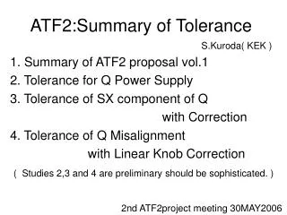
ATF2:Summary of Tolerance S.Kuroda( KEK ) 1. Summary of ATF2 proposal vol.1 2. Tolerance for Q Power Supply 3. Tolerance of SX component of Q with Correction 4. Tolerance of Q Misalignment with Linear Knob Correction ( Studies 2,3 and 4 are preliminary should be sophisticated. ) 2nd ATF2project meeting 30MAY2006
1. Summary of ATF2 proposal vol.1 Tolerable field ratio at r=10mm for 2% beam size growth [J.Jones]
Summary of ATF2 proposal vol.1(cont.) Vibration tolerance for 2% beam size growth [A.Seryi]
2. Tolerance for Q Power Supply Qs are classified into 5 groups( cf. Kumada case1 ) QD0, QF1, QD4&10, QM, others In this simulation, for each Q, K1 error is dK1/K1=s maxK1/K1 Here maxK1 is maximum Abs[K1] of the group and s =10ppm(QD0) 30ppm(QF1, QD4&10) sx(QM, others) Sim. Cond. ex=2e-9,gey=3e-8, d=8e-4 ideal sy=34.8nm sx =100ppm Gaussian error dist. sy(95%CL)=48nm sx =100ppm Uniform error dist. sy(95%CL)=38.5nm sx =250ppm Uniform error dist. sy(95%CL)=52nm
3. Tolerance of SX component of Q with Correction sigx sigy Gaussian error dB2/B1@r=10mm =1e-4 for FD =1e-3 for 20cm Q Correction Knob: SX Trial and error looking at sy step: dK2=1e-2 Perfect BSM resolution is assumed After Correction
=1e-3(for 20cm Q) variable(for FD) Tolerance of SX component of Q with Correction( cont. ) dK2=2 sgn K1 /r (r=10mm, sgn=1: random for each Q) dK2=+2 K1 /r (r=10mm) dK2=-2 K1 /r (r=10mm) Example:dFD=5e-4 Corr It seems OK for dFD=5e-4.
dK2=2 sgn K1 /r Sin[q], dSK2=2 sgn K1 /r Cos[q] (r=10mm, sgn=1: random for each Q,0<q<2p:uniformly random) Tolerance of SX component of Q with Correction(cont.2) Correction: roll(1mrad step) of SX+K2(1% step) of SX dFD=1e-4 After cor., sy(95%CL)=44nm Iteration of correction x2 sy(95%CL)=47nm Iteration of cor. is not effective Cor. dFD=5e-4, d20cmQ=5e-4 After cor., sy(95%CL)=225nm SK2 of FD affects significantly to sy. Tolerance of SK2 should be much less than 1e-4. Cor.
4. Tolerance of Q Misalignment with Linear Knob Correction Correction Order: R2,R1,WY,PEY Correction step: WaistY:1mm(sy>1mm) 100mm(sy>100nm) 20mm(sy<100nm) R1:1e-2 (sy>1mm) 1e-3(sy>100nm) 1e-4(sy<100nm) R2:1e-3 (sy>1mm) 1e-4(sy>100nm) 2e-5(sy<100nm) PEY: 10mm because of the resolution of the sy calculation by tracking(NP=1000) Knob Mover of SX DXWaistX, WaistY, PEX DYPEY, Coupling(R1,R2) Each knobs are orthogonalized by linear combination Performance for Single Type of Error of Q Gaussian error is assumed. Iterative correction was done for errors DY and Roll. dX dY dK1 d 4e-5 2e-5 1e-6 5e-4 95% CL values are plotted.
Tolerance of Q Misalignment with Linear Knob Correction( cont. ) All types of errors (dK1/K1, dx, dy, roll)=a(5e-4, 40mm, 20mm,100mrad) Correction # of iteration ≤ 5 Iteration stops if sy≤ 35nm For a<0.7, sy<40nm after correction Mover Spec. Requirement Minimum step min. coeff. knob min.step WY:2e-5 SF1_DX=-0.0121574 wy 2.4e-7 PEY:1e-5 SD4_DY= -0.186651 py 1.9e-6 R1:1e-4 SD0_DY= -0.220771 r1 2.2e-5 R2:2e-5 SD0_DY= -0.127017 r1 2.5e-6 Dynamic range For a=0.6 max. coeff. knob max.step maxWY:1.98e-3 SD4_DX= 0.0721866 wy 1.4e-4 maxPEY:3e-4 SD0_DY= 0.429982 py 1.3e-4 maxR1:1.3e-3 SF6_DY= 0.526463 r1 6.5e-4 maxR2:3.8e-3 SF6_DY= 0.387005 r1 1.5e-3
Summary & Discussion • Tolerances for multipole component of Q & vibration are reviewed( proposal vol.1 ). • Some results of study for tolerance with correction are reported. But these are not completed and to be done more; 1. Higher order parameters should be included in the knobs. Then SX strength will be used as a part, so the correction for the SX component of Q should be done again. 2. Optics for the study should be updated. 3. Tolerance for FD is defined separately with the other Q( ? )