Download
1 / 80
830 likes | 1.07k Vues
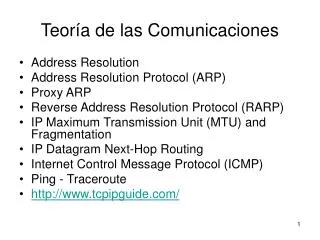
Teoría de las Comunicaciones. Address Resolution Address Resolution Protocol (ARP) Proxy ARP Reverse Address Resolution Protocol (RARP) IP Maximum Transmission Unit (MTU) and Fragmentation IP Datagram Next-Hop Routing Internet Control Message Protocol (ICMP) Ping - Traceroute

E N D
Teoría de las Comunicaciones • Address Resolution • Address Resolution Protocol (ARP) • Proxy ARP • Reverse Address Resolution Protocol (RARP) • IP Maximum Transmission Unit (MTU) and Fragmentation • IP Datagram Next-Hop Routing • Internet Control Message Protocol (ICMP) • Ping - Traceroute • http://www.tcpipguide.com/
Why Address Resolution Is Necessary • In this example, a client on the local network is accessing a server somewhere on the Internet. Logically, this connection can be made “directly” between the client and server, but in reality it is a sequence of physical links at layer two. In this case there are six such links, most of them between routers that lie between the client and server. At each step the decision of where to send the data is made based on a layer three address, but the actual transmission must be performed using the layer two address of the next intended recipient in the route.
Address resolution • Key Concept: Address resolution is required because internetworked devices communicate logically using layer three addresses, but the actual transmissions between devices take place using layer two (hardware) addresses.
Address Resolution Through Direct Mapping • Key Concept: When the layer two address is smaller than the layer three address, it is possible to define a direct mapping between them, so that the hardware address can be determined directly from the network layer address. This makes address resolution extremely simple, but reduces flexibility in how addresses are assigned.
Address Resolution Protocol (ARP) • Device A needs to send data to Device B but knows only its IP address (“IPB”), and not its hardware address. A broadcasts a request asking to be sent the hardware address of the device using the IP address “IPB”. B responds back to A directly with the hardware address
Dynamic address resolution • Key Concept: Dynamic address resolution is usually implemented using a special protocol. A device that knows only the network layer address of another device can use this protocol to request the other device’s hardware address.
ARP • Key Concept: ARP was developed to facilitate dynamic address resolution between IP and Ethernet, and can now be used on other layer two technologies as well. It works by allowing an IP device to send a broadcast on the local network, requesting that another device on the same local network respond with its hardware address.
Address Resolution Protocol (ARP) Transaction Process • This diagram shows the sequence of steps followed in a typical ARP transaction, as well as the message exchanges between a source and destination device, and cache checking and update functions.
ARP • Key Concept: ARP is a relatively simple request/reply protocol. The source device broadcasts an ARP Request looking for a particular device based on its IP address. That device responds with its hardware address in an ARP Reply message.
Address Resolution Protocol (ARP) Message Format • The ARP message format is designed to accommodate layer two and layer three addresses of various sizes. This diagram shows the most common implementation, which uses 32 bits for the layer three (“Protocol”) addresses, and 48 bits for the layer two hardware addresses. These numbers of course correspond to the address sizes of the Internet Protocol version 4 and IEEE 802 MAC addresses, used by Ethernet
Proxy ARP • In contrast to the normal situation, in some networks there might be two physical network segments connected by a router that are in the same IP network or subnetwork. In other words, device A and device B might be on different networks at the data link layer level, but on the same IP network or subnet. When this happens, A and B will each think the other is on the local network when they look to send IP datagrams. In this situation, suppose that A wants to send a datagram to B. It doesn't have B's hardware address in the cache, so it begins an address resolution. When it broadcasts the ARP Request message to get B's hardware address, however, it will quickly run into a problem: B is in fact not on A's local network. The router between them will not pass A's broadcast onto B's part of the network, because routers don't pass hardware-layer broadcasts. B will never get the request and thus A will not get a reply containing B’s hardware address.
ARP Proxy Operation • In this small internetwork, a single router connects two LANs that are on the same IP network or subnet. The router will not pass ARP broadcasts, but has been configured to act as an ARP proxy. In this example, device A and device D are each trying to send an IP datagram to the other, and so each broadcasts an ARP Request. The router responds to the request sent by Device A as if it were Device D, giving to A its own hardware address (without propagating Device A’s broadcast.) It will forward the message sent by A to D on D’s network. Similarly, it responds to Device D as if it were Device A, giving its own address, then forwarding what D sends to it over to the network where A is located.
Proxy ARP • Key Concept: Since ARP relies on broadcasts for address resolution, and broadcasts are not propagated beyond a physical network, ARP cannot function between devices on different physical networks. When such operation is required, a device, such as a router, can be configured as an ARP proxy to respond to ARP requests on the behalf of a device on a different network.
Reverse Address Resolution Protocol (RARP) • The first method devised to address the bootstrapping problem in TCP/IP was the backwards use of ARP I mentioned above. This technique was formalized in RFC 903, A Reverse Address Resolution Protocol (RARP), published in 1984. Where ARP allows device A to say “I am device A and I have device B's IP address, device B please tell me your hardware address”, RARP is used by device A to say “I am device A and I am sending this broadcast using my hardware address, can someone please tell me my IP address?”.
Operation of the Reverse Address Resolution Protocol (RARP) • RARP, as the name suggests, works like ARP but in reverse, so this diagram is similar. Here, instead of Device A providing the IP address of another device and asking for its hardware address, it is providing its own hardware address and asking for an IP address it can use. The answer, in this case, is provided by Device D, which is serving as an RARP server for this network.
RARP • Key Concept: The Reverse Address Resolution Protocol (RARP) is the earliest and simplest protocol designed to allow a device to obtain an IP address for use on a TCP/IP network. It is based directly on ARP and works in basically the same way, but in reverse: a device sends a request containing its hardware address and a device set up as an RARP server responds back with the device’s assigned IP address.
RARP • Today, the importance of host configuration has increased since the early 1980s. Many organizations assign IP addresses dynamically even for hosts that have disk storage, because of the many advantages this provides in administration and efficient use of address space. For this reason, RARP has been replaced by two more capable technologies that operate at higher layers in the TCP/IP protocol stack: BOOTP and DHCP.
The Main Function of IP: Internetwork Datagram Delivery • The fundamental job of the Internet Protocol is the delivery of datagrams from one device to another over an internetwork. In this generic example, a distant client and server communicate with each other by passing IP datagrams over a series of interconnected networks.
IP • Key Concept: While the Internet Protocol has many functions and characteristics, it can be boiled down to one primary purpose: the delivery of datagrams across an internetwork of connected networks.
IP Interfaces for Common Network Devices • This illustration shows the IP interfaces of a few common of LAN devices as small cyan circles. Each regular host has one interface, while the router that serves this LAN has three, since it connects to three different networks. Note that the LAN switch has no IP interfaces; it connects the hosts and router at layer two. Also see Figure 59, which shows the IP interfaces of devices in a more complex configuration.
IP Datagram Encapsulation • Very similar drawing for the OSI Reference Model as a whole, showing specifically how data encapsulation is accomplished in TCP/IP. As you can see, an upper layer message is packaged into a TCP or UDP message. This then becomes the payload of an IP datagram, which is shown here simply with one header (things can get a bit more complex than this.) The IP datagram is then passed down to layer 2 where it is in turn encapsulated into some sort of LAN, WAN or WLAN frame, then converted to bits and transmitted at the physical layer.
Internet Protocol Version 4 (IPv4) Datagram Format • This diagram shows graphically the all-important IPv4 datagram format. The first 20 bytes are the fixed IP header, followed by an optional Options section, and a variable-length Data area. Note that the Type Of Service field is shown as originally defined in the IPv4 standard.
IP • Key Concept: Each IPv4 datagram has a 20-byte mandatory header, and may also include one or more options. Each option has its own field format, and most are variable in size.
IP • Key Concept: The size of the largest IP datagram that can be transmitted over a physical network is called that network’s maximum transmission unit (MTU). If a datagram is passed from a network with a high MTU to one with a low MTU, it must be fragmented to fit the network with the smaller MTU.
IP Maximum Transmission Unit (MTU) and Fragmentation • In this simple example, Device A is sending to Device B over a small internetwork consisting of one router and two physical links. The link from A to the router has an MTU of 3,300 bytes, but from the router to B it is only 1,300 bytes. Thus, any IP datagrams over 1,300 bytes will need to be fragmented.
IPv4 Datagram Fragmentation • This example shows illustrates a two-step fragmentation of a large IP datagram. The boxes represent datagrams or datagram fragments and are shown to scale. The original datagram is 12,000 bytes in size, represented by the large gray box. To transmit this data over the first local link, Device A splits it into four fragments, shown at left in four primary colors. The first router must fragment each of these into smaller fragments to send them over the 1,300-byte MTU link, as shown on the bottom. Note that the second router does not reassemble the 1,300-byte fragments, even though its link to Device B has an MTU of 3,300 bytes.
IPv4 Datagram Fragmentation Process • In this diagram, the MF and Fragment Offset fields of each fragment are shown for reference. The Data fields are shown to scale (the length of each is proportional to the number of bytes in the fragment.)
IP Fragmentation • Key Concept: When an MTU requirement forces a datagram to be fragmented, it is split into several smaller IP datagrams, each containing part of the original. The header of the original datagram is changed into the header of the first fragment, and new headers are created for the other fragments. Each is set to the same Identification value to mark them as part of the same original datagram. The Fragment Offset of each is set to the location where the fragment belongs in the original. The More Fragments field is set to 1 for all fragments but the last, to let the recipient know when it has received all the fragments.
IP Fragmentation • Key Concept: In IPv4, fragmentation can be performed by a router between the source and destination of an IP datagram, but reassembly is only done by the destination device.
Direct and Indirect (Routed) Delivery of IP Datagrams • This diagram shows three examples of IP datagram delivery. The first transmission (highlighted in green) shows a direct delivery between two devices on the local network. The second (purple) shows indirect delivery within the local network, between a client and server separated by a router. The third shows a more distant indirect delivery, between a client on the local network and a server across the Internet.
Direct and Indirect (Routed) Delivery of IP Datagrams • Key Concept: The delivery of IP datagrams is divided into two categories: direct and indirect. Direct delivery is possible when two devices are on the same physical network. When they are not, indirect delivery, more commonly called routing, is required to get the datagrams from source to destination. A device can tell which type of delivery is required by looking at the IP address of the destination, in conjunction with supplemental information such as the subnet mask that tells the device what network or subnet it is on.
IP Datagram Next-Hop Routing • This time I have explicitly shown the hops taken by each of the three sample transmissions. The direct delivery of the first (green) transmission has only one hop (remember that the switch doesn’t count because it is invisible at layer three). The local indirect delivery passes through one router, so it has two hops. The Internet delivery in this case has six hops; actual Internet routes can be much longer.
IP Datagram Next-Hop Routing • Key Concept: Indirect delivery of IP datagrams is accomplished using a process called next-hop routing, where each message is handed from one router to the next until it reaches the network of the destination. The main advantage of this is that each router needs only to know which neighboring router should be the next recipient of a given datagram, rather than needing to know the exact route to every destination network.