Alex Bogacz
Lattice Design Choices for LHeC ERL. Alex Bogacz. Jefferson Lab March 17-20, 2014 . Linac -Ring Option - LHeC ERL Recirculator. F. Zimmermann. total circumference ~ 8.9 km.

Alex Bogacz
E N D
Presentation Transcript
Lattice Design Choices for LHeC ERL • Alex Bogacz Jefferson Lab March 17-20, 2014 EIC14 Workshop, Jefferson Lab, March 20, 2014
Linac-Ring Option -LHeC ERL Recirculator F. Zimmermann total circumference ~ 8.9 km The baseline 60 GeV ERL option proposed can give an e-p luminosity of 1033 cm-2s-1 (extensions to 1034 cm-2s-1 and beyond are being considered) EIC14 Workshop, Jefferson Lab, March 20, 2014
Why Energy Recovering RLA? • High energy (60 GeV), high current (6.4 mA) beams: (384 MW beam power) would require sub GW (0.8 GW)-class RF systems in conventional linacs . • Invoking Energy Recovery alleviates extreme RF power demand (power reduced by factor (1 -hERL) ⇨ Required RF power becomes nearly independent of beam current. • Energy Recovering Linacs promise efficiencies of storage rings, while maintaining beam quality of linacs: superior emittance and energy spread and short bunches (sub-pico sec.). • GeV scale Energy Recovery demonstration with high ER ratio (hERL = 0.98) was carried out in a large scale SRF Recirculating Linac (CEBAF ER Exp. in 2003) • No adverse effects of ER on beam quality or RF performance: gradients, Q, cryo-load observed – mature and reliable technology (next generation light sources) EIC14 Workshop, Jefferson Lab, March 20, 2014
LHeCRecirculatorwith ER injector 0.5 GeV Linac 1 10 GeV/pass Arc1, 3, 5 dump Arc 2, 4, 6 + l/2 0.5 GeV Linac 2 10 GeV/pass IP 60 GeV LHC EIC14 Workshop, Jefferson Lab, March 20, 2014
LHeCRecirculatorwith ER injector 0.5 GeV Linac 1 10 GeV/pass Arc1, 3, 5 dump Arc 2, 4, 6 + l/2 0.5 GeV Linac 2 10 GeV/pass IP 60 GeV LHC EIC14 Workshop, Jefferson Lab, March 20, 2014
LHeCRecirculatorwith ER injector 0.5 GeV Linac 1 10 GeV/pass Arc1, 3, 5 dump Arc 2, 4, 6 + l/2 0.5 GeV Linac 2 10 GeV/pass IP 60 GeV LHC EIC14 Workshop, Jefferson Lab, March 20, 2014
ERL–Ring: Dimensions/Layout J. Osborne IP EIC14 Workshop, Jefferson Lab, March 20, 2014
Beam Dynamics Challenges/Mitigations • Incoherent and coherent synchrotron radiation related effects on the electron beam • energy losses Size/Layout • longitudinal emittance increase Size/Layout • transverse emittance increase Lattice • Beam Breakup Instability (BBU) • single beam Lattice • multi-pass Lattice • Depolarization effects Lattice EIC14 Workshop, Jefferson Lab, March 20, 2014
5 160 BETA_X&Y[m] 0 0 0 BETA_X BETA_Y DISP_X DISP_Y 29.6 Cryo Unit Layout/Optics - Half-Cell 1300 FODO ×38 Lc quad Cavity Cryo: 8 RF cavities Cavity Cryo: 8 RF cavities 802 MHz RF, 5-cell cavity: l = 37.38 cm Lc = 5l/2 = 93.45 cm Grad = 18 MeV/m (16.8 MeV per cavity) DE= 269.14 MV per Cryo Unit D. Schulte EIC14 Workshop, Jefferson Lab, March 20, 2014
5 200 BETA_X&Y[m] DISP_X&Y[m] 0 0 0 BETA_X BETA_Y DISP_X DISP_Y 1008 10 GeVLinac- Focusing profile E = 0.5 - 10.5 GeV quad gradient 19 FODO cells (19 × 2 × 16 = 608 RF cavities) EIC14 Workshop, Jefferson Lab, March 20, 2014
Linac 1 - Multi-pass ER Optics EIC14 Workshop, Jefferson Lab, March 20, 2014
Linac 1 and 2 - Multi-pass ER Optics EIC14 Workshop, Jefferson Lab, March 20, 2014
Arc Optics – Beam Dynamics Issues • Natural momentum spread due to quantum excitations: • Emittancedilution due to quantum excitations: • Momentum Compaction – synchronous acceleration in the linacs: EIC14 Workshop, Jefferson Lab, March 20, 2014
150 1.5 BETA_X&Y[m] DISP_X&Y[m] -1.5 0 0 BETA_X BETA_Y DISP_X DISP_Y 52.3599 1350 FODO Cell EIC14 Workshop, Jefferson Lab, March 20, 2014
150 0.3 BETA_X&Y[m] DISP_X&Y[m] -0.3 0 0 BETA_X BETA_Y DISP_X DISP_Y 52.3599 Flexible Momentum Compaction (FMC) Cell Emittance dispersion 〈H〉avereged over bends Momentum compaction factor of 2.5 smaller than 1350 FODO factor of 27 smaller than 1350 FODO EIC14 Workshop, Jefferson Lab, March 20, 2014
500 0.5 500 500 0.5 0.5 BETA_X&Y[m] DISP_X&Y[m] BETA_X&Y[m] BETA_X&Y[m] DISP_X&Y[m] DISP_X&Y[m] -0.5 -0.5 -0.5 0 0 0 0 BETA_X BETA_Y DISP_X 52.3599 DISP_Y 0 BETA_X BETA_Y DISP_X DISP_Y 52.3599 0 BETA_X BETA_Y DISP_X 52.3599 DISP_Y Arc Optics – Emittance preserving FMC cell Arc 1 , Arc2 Arc 3, Arc 4 Arc5, Arc 6 Imaginary gt Optics TME-like Optics DBA-like Optics factor of 18 smaller than FODO total emittance increase in Arc 5:DexN = 4.268 mm rad EIC14 Workshop, Jefferson Lab, March 20, 2014
Energy Loss and Emittance Dilution in Arcs A. Valloni EIC14 Workshop, Jefferson Lab, March 20, 2014
Vertical Separation of Arcs Arc 1 (10 GeV) Arc 3 (30 GeV) Arc 5 (50 GeV) EIC14 Workshop, Jefferson Lab, March 20, 2014
600 0.6 BETA_X&Y[m] DISP_X&Y[m] -0.6 0 0 BETA_X BETA_Y DISP_X DISP_Y 76 600 0.6 BETA_X&Y[m] DISP_X&Y[m] -0.6 0 0 BETA_X BETA_Y DISP_X DISP_Y 76 600 0.6 BETA_X&Y[m] DISP_X&Y[m] -0.6 0 0 BETA_X BETA_Y DISP_X DISP_Y 76 Vertical Spreaders - Optics Spr. 1 path-length adjustment ‘doglegs’ vertical step I vertical step II Spr. 3 path-length adjustment ‘doglegs’ vertical step I vertical step II Spr. 5 path-length adjustment ‘doglegs’ vertical chicane EIC14 Workshop, Jefferson Lab, March 20, 2014
Vertical Separation of Arcs Arc 1 (10 GeV) Arc 3 (30 GeV) Arc 5 (50 GeV) EIC14 Workshop, Jefferson Lab, March 20, 2014
600 0.6 600 0.6 BETA_X&Y[m] DISP_X&Y[m] BETA_X&Y[m] DISP_X&Y[m] -0.6 -0.6 0 0 3060 BETA_X BETA_Y DISP_X DISP_Y 3292.61 0 BETA_X BETA_Y DISP_X DISP_Y 230 Arc 1 Optics (10 GeV) doglegs vert. 2-step recombiner doglegs vert. 2-step spreader dis. sup. cell dis. sup. cell 58 FMC cells 180 deg. Arc Arc dipoles: $Lb=400 cm $B=0.47 kGauss EIC14 Workshop, Jefferson Lab, March 20, 2014
600 600 0.6 0.6 BETA_X&Y[m] BETA_X&Y[m] DISP_X&Y[m] DISP_X&Y[m] -0.6 -0.6 0 0 0 BETA_X BETA_Y DISP_X DISP_Y 230 3060 BETA_X BETA_Y DISP_X DISP_Y 3292.58 Arc 3 Optics (30 GeV) doglegs vert. 2-step recombiner doglegs vert. 2-step spreader dis. sup. cell dis. sup. cell 58 FMC cells 180 deg. Arc Arc dipoles: $Lb=400 cm $B=1.37 kGauss EIC14 Workshop, Jefferson Lab, March 20, 2014
Vertical Stack - Combined Aperture Arc Dipole 0.264 T 60 GeV 0.176 T 40 GeV ∙ ∙ ∙ ∙ × × × × 0.088 T 20GeV A. Milanese EIC14 Workshop, Jefferson Lab, March 20, 2014
Summary • High luminosity Linac-Ring option - ERL • RF power nearly independent of beam current. • Multi-pass linac Optics in ER mode • Choice of linac RF and Optics -802 MHz SRF and 1300 FODO • Linear lattice: 3-pass ‘up’ + 3-pass ‘down’ • Arc Optics Choice -Emittance preserving lattices • Quasi-isochronous lattices • Flexible Momentum Compaction Optics • Balanced emittance dilution & momentum compaction • Complete Arc Architecture • Vertical switchyard • Matching sections & path-length correcting ‘doglegs’ • Alternative ERL Topology - ‘Dogbone’ Option? EIC14 Workshop, Jefferson Lab, March 20, 2014
Special Thanks to: Frank Zimmermann Daniel Schulte Erk Jensen Oliver Brüning and Max Klein EIC14 Workshop, Jefferson Lab, March 20, 2014
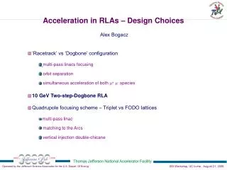
‘Racetrack’ vs ‘Dogbone’ RLA Twice the acceleration efficiency for the ‘Dogbone’ topology DE/2 1.5 DE DE/2 DE 3 DE Challenge: traversing linac in both directions while accelerating EIC14 Workshop, Jefferson Lab, March 20, 2014
‘Dogbone’ vs ‘Racetrack’ – Arc-length 9×DE/2 9×DE/2 =n(p + 4a)R n× a a =2npR 2n× Net arc-length break even: if a = p/4 EIC14 Workshop, Jefferson Lab, March 20, 2014
Future Muon Facilities -Muon Acceleration n to Homestake Neutrino Factory LBNE Higgs Factory RLA to 63 GeV NF Decay Ring Linac + RLA to 4 GeV Project XStage III Project XStage II Project XStage I J.-P. Delahaye, MASS (Muon Accelerator Staging Studies) Fermilab EIC14 Workshop, Jefferson Lab, March 20, 2014
Droplet Arcs - Layout top view 1.2 GeV 2.4 GeV side view 1.2 GeV 1 m 2.4 GeV EIC14 Workshop, Jefferson Lab, March 20, 2014
‘Racetrack’ vs ‘Dogbone’ ERL for LHeC 3-pass RLA Baseline 0.5 GeV 10 GeV 20 GeV 10 GeV linac 30 GeV 40 GeV 0.5 GeV 50 GeV 60 GeV IP 10 GeV linac 60 GeV 5-pass RLA ‘Dogbone’ 24GeV 12 GeV 36 GeV 0.5 GeV 48 GeV 60 GeV IP 12 GeVlinac 0.5 GeV 60 GeV EIC14 Workshop, Jefferson Lab, March 20, 2014
‘Dogbone’ RLA - Multi-pass Linac Optics Acceleration Deceleration EIC14 Workshop, Jefferson Lab, March 20, 2014
Pros and Cons of a ‘Dogbone’ RLA • High acceleration efficiency (≤2) – traversing the linac in both directions while accelerating • Better orbit separation at linac’s end ~ energy difference between consecutive passes (2DE) vs (DE) in case of the ‘Racetrack’ • Suppression of depolarizationeffects Beam trajectory can be made to follow a Figure-8 path (by reversing field directions in opposing droplet arcs) • Beams of different energies moving in the opposite direction through the linac – orbit separation needed to avoid parasitic collisions. • As linac length and number of passes are increased, the BBU threshold can be a problem. • Travelling ‘clearing gaps’ to alleviate ion trapping- No practical solution found EIC14 Workshop, Jefferson Lab, March 20, 2014