Disk-based Storage Oct. 23, 2008
Disk-based Storage Oct. 23, 2008. 15-213 “The course that gives CMU its Zip!”. Topics Storage technologies and trends Locality of reference Caching in the memory hierarchy. lecture-17.ppt. Announcements. Exam next Thursday style like exam #1: in class, open book/notes, no electronics.

Disk-based Storage Oct. 23, 2008
E N D
Presentation Transcript
Disk-based StorageOct. 23, 2008 15-213“The course that gives CMU its Zip!” Topics • Storage technologies and trends • Locality of reference • Caching in the memory hierarchy lecture-17.ppt
Announcements Exam next Thursday • style like exam #1: in class, open book/notes, no electronics
Disk-based storage in computers • Memory/storage hierarchy • Combining many technologies to balance costs/benefits • Recall the memory hierarchy and virtual memory lectures
Performance Capacity Memory/storage hierarchies • Balancing performance with cost • Small memories are fast but expensive • Large memories are slow but cheap • Exploit locality to get the best of both worlds • locality = re-use/nearness of accesses • allows most accesses to use small, fast memory
L1 cache holds cache lines retrieved from the L2 cache memory. L2 cache holds cache lines retrieved from main memory. Main memory holds disk blocks retrieved from local disks. Local disks hold files retrieved from disks on remote network servers. An Example Memory Hierarchy Smaller, faster, and costlier (per byte) storage devices L0: registers CPU registers hold words retrieved from L1 cache. on-chip L1 cache (SRAM) L1: off-chip L2 cache (SRAM) L2: main memory (DRAM) L3: Larger, slower, and cheaper (per byte) storage devices local secondary storage (local disks) L4: remote secondary storage (tapes, distributed file systems, Web servers) L5: From lecture-9.ppt
Page Faults A page fault is caused by a reference to a VM word that is not in physical (main) memory • Example: An instruction references a word contained in VP 3, a miss that triggers a page fault exception Physical memory (DRAM) Physical page number or disk address Virtual address PP 0 VP 1 Valid VP 2 PTE 0 0 null VP 7 1 PP 3 VP 4 1 0 1 Virtual memory (disk) 0 null 0 PTE 7 1 VP 1 Memory resident page table (DRAM) VP 2 VP 3 VP 4 VP 6 VP 7 From lecture-14.ppt
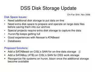
Disk-based storage in computers • Memory/storage hierarchy • Combining many technologies to balance costs/benefits • Recall the memory hierarchy and virtual memory lectures • Persistence • Storing data for lengthy periods of time • DRAM/SRAM is “volatile”: contents lost if power lost • Disks are “non-volatile”: contents survive power outages • To be useful, it must also be possible to find it again later • this brings in many interesting data organization, consistency, and management issues • take 18-746/15-746 Storage Systems • we’ll talk a bit about file systems next
What’s Inside A Disk Drive? Spindle Arm Platters Actuator Electronics SCSI connector Image courtesy of Seagate Technology
Disk Electronics Just like a small computer – processor, memory, network iface • Connect to disk • Control processor • Cache memory • Control ASIC • Connect to motor
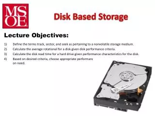
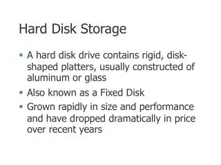
Disk “Geometry” Disks contain platters, each with two surfaces Each surface organized in concentric rings called tracks Each track consists of sectors separated by gaps tracks surface track k gaps spindle sectors
Disk Geometry (Muliple-Platter View) Aligned tracks form a cylinder cylinder k surface 0 platter 0 surface 1 surface 2 platter 1 surface 3 surface 4 platter 2 surface 5 spindle
Arm Read/Write Head Upper Surface Platter Lower Surface Cylinder Track Sector Actuator Disk Structure
The read/write head is attached to the end of the arm and flies over the disk surface on a thin cushion of air By moving radially, the arm can position the read/write head over any track Disk Operation (Single-Platter View) The disk surface spins at a fixed rotational rate spindle spindle spindle spindle spindle
Disk Operation (Multi-Platter View) read/write heads move in unison from cylinder to cylinder arm spindle
Surface organized into tracks Tracks divided into sectors Disk Structure - top view of single platter
Disk Access Head in position above a track
Disk Access Rotation is counter-clockwise
Disk Access – Read About to read blue sector
Disk Access – Read After BLUEread After reading blue sector
Disk Access – Read After BLUEread Red request scheduled next
Disk Access – Seek After BLUEread Seek for RED Seek to red’s track
Disk Access – Rotational Latency After BLUEread Seek for RED Rotational latency Wait for red sector to rotate around
Disk Access – Read After BLUEread Seek for RED Rotational latency After RED read Complete read of red
Disk Access – Service Time Components After BLUEread Seek for RED Rotational latency After RED read Seek Rotational Latency Data Transfer
Disk Access Time Average time to access a specific sector approximated by: • Taccess = Tavg seek + Tavg rotation + Tavg transfer Seek time (Tavg seek) • Time to position heads over cylinder containing target sector • Typical Tavg seek = 3-5 ms Rotational latency (Tavg rotation) • Time waiting for first bit of target sector to pass under r/w head • Tavg rotation = 1/2 x 1/RPMs x 60 sec/1 min • e.g., 3ms for 10,000 RPM disk Transfer time (Tavg transfer) • Time to read the bits in the target sector • Tavg transfer = 1/RPM x 1/(avg # sectors/track) x 60 secs/1 min • e.g., 0.006ms for 10,000 RPM disk with 1,000 sectors/track • given 512-byte sectors, ~85 MB/s data transfer rate
Disk Access Time Example Given: • Rotational rate = 7,200 RPM • Average seek time = 5 ms • Avg # sectors/track = 1000 Derived average time to access random sector: • Tavg rotation = 1/2 x (60 secs/7200 RPM) x 1000 ms/sec = 4 ms • Tavg transfer = 60/7200 RPM x 1/400 secs/track x 1000 ms/sec = 0.008 ms • Taccess = 5 ms + 4 ms + 0.008 ms = 9.008 ms • Time to second sector: 0.008 ms Important points: • Access time dominated by seek time and rotational latency • First bit in a sector is the most expensive, the rest are free • SRAM access time is about 4 ns/doubleword, DRAM about 60 ns • ~100,000 times longer to access a word on disk than in DRAM
… … 5 6 7 12 23 Disk storage as array of blocks OS’s view of storage device (as exposed by SCSI or IDE/ATA protocols) • Common “logical block” size: 512 bytes • Number of blocks: device capacity / block size • Common OS-to-storage requests defined by few fields • R/W, block #, # of blocks, memory source/dest
Page Faults A page fault is caused by a reference to a VM word that is not in physical (main) memory • Example: An instruction references a word contained in VP 3, a miss that triggers a page fault exception “logical block” number can be remembered in page table to identify disk location for pages not resident in main memory Physical memory (DRAM) Physical page number or disk address Virtual address PP 0 VP 1 Valid VP 2 PTE 0 0 null VP 7 1 PP 3 VP 4 1 0 1 Virtual memory (disk) 0 null 0 PTE 7 1 VP 1 Memory resident page table (DRAM) VP 2 VP 3 VP 4 VP 6 VP 7 From lecture-14.ppt
Disk Sector (usually same size as block) In device, “blocks” mapped to physical store
16 17 15 18 29 28 27 30 41 40 42 39 14 19 26 31 38 43 37 44 25 32 20 36 45 46 47 33 24 34 35 21 22 23 LBN-to-physical for a single-surface disk 5 4 3 6 7 2 13 1 8 12 9 0 10 11
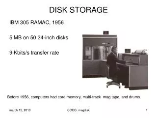
Disk Capacity Capacity: maximum number of bits that can be stored • Vendors express capacity in units of gigabytes (GB), where1 GB = 109 Bytes (Lawsuit pending! Claims deceptive advertising) Capacity is determined by these technology factors: • Recording density (bits/in): number of bits that can be squeezed into a 1 inch linear segment of a track • Track density (tracks/in): number of tracks that can be squeezed into a 1 inch radial segment • Areal density (bits/in2): product of recording and track density
Computing Disk Capacity Capacity = (# bytes/sector) x (avg. # sectors/track) x (# tracks/surface) x (# surfaces/platter) x (# platters/disk) Example: • 512 bytes/sector • 1000 sectors/track (on average) • 20,000 tracks/surface • 2 surfaces/platter • 5 platters/disk Capacity = 512 x 1000 x 80000 x 2 x 5 = 409,600,000,000 = 409.6 GB
Looking back at the hardware CPU chip register file ALU main memory bus interface
I/O bus Expansion slots for other devices such as network adapters USB controller graphics adapter disk controller mouse keyboard monitor disk Connecting I/O devices: the I/O Bus CPU chip register file ALU system bus memory bus main memory bus interface I/O bridge
Reading from disk (1) CPU chip CPU initiates a disk read by writing a READ command, logical block number, number of blocks, and destination memory address to a port (address) associated with disk controller register file ALU main memory bus interface I/O bus USB controller graphics adapter disk controller mouse keyboard monitor disk
Reading from disk (2) CPU chip Disk controller reads the sectors and performs a direct memory access (DMA) transfer into main memory register file ALU main memory bus interface I/O bus USB controller graphics adapter disk controller mouse keyboard monitor disk
Reading from disk (3) CPU chip When the DMA transfer completes, the disk controller notifies the CPU with an interrupt (i.e., asserts a special “interrupt” pin on the CPU) register file ALU main memory bus interface I/O bus USB controller graphics adapter disk controller mouse keyboard monitor disk