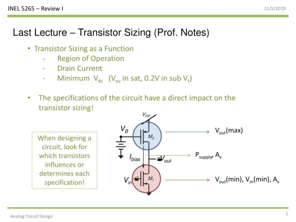
Post-Layout Transistor Sizing Optimization for Crosstalk Noise Reduction
200 likes | 231 Vues
Learn about effective post-layout transistor sizing optimization techniques to minimize crosstalk noise and preserve interconnects, achieving up to 50% peak noise reduction. This study includes noise estimation, noise optimization algorithms, experimental results, and conclusions on RC tree optimization on LSI.

Post-Layout Transistor Sizing Optimization for Crosstalk Noise Reduction
E N D
Presentation Transcript
Crosstalk Noise Optimization by Post-Layout Transistor Sizing Masanori Hashimoto Masao Takahashi Hidetoshi Onodera Dept. CCE, Kyoto University
Post-Layout Tr. Sizing for Crosstalk Noise Reduction Overview • Crosstalk noise depends on • coupling length • coupling position • driver strength of aggressor • hold strength of victim • Use analytic noise model • suitable for a lot of repetitive noise estimation • Optimize Tr. sizes preserving interconnects • no iterations between Tr. sizing and layout Routing & interconnect optimization Our target
Post-Layout Tr. Sizing for Crosstalk Noise Reduction Features Optimization with interconnect preservation • no iterations between layout and Tr. sizing • accurately-extracted coupling information Downsize too strong drivers • continuous sizing • vary PN ratio • consider noise margin and transition time constraints
Shrink Tr. width Terminals are fixed. On-Demand Cell Layout Generation(VARDS) Half size Normal size Same height
Contents • Crosstalk noise estimation • Noise optimization algorithm • Experimental results • Conclusion
Generic RC Trees on LSI Multiple aggressors, multiple branches aggressor 1 branch 2 branch 1 victim aggressor 2 aggressor 3
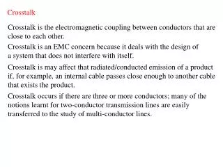
Crosstalk Noise EstimationOverview • Noise estimation for two partially-coupled interconnects • closed-form noise waveform • Multiple aggressors • superpose noises from each aggressor • Multiple sinks • transform into two partially-coupled interconnects Aggressor Victim
Modeling of Two Partially-Coupled Interconnects Vagg(t) aggressor model Vagg(t) Vnoise(t) victim model
Cc Vagg Rv1 Rv2 Rv3 Vnoise Cv2 Cv3 Cv1 Noise Waveform and Peak Noise Voltage noise waveform peak noise
Multiple Aggressors aggressor 1 Vnoise(t) victim aggressor n aggressor 1 Vnoisen(t) Vnoise1(t) aggressor n Superposition Vnoise(t)=Vnoise1(t)+・・・+Vnoisen(t)
Superposition Considering Timing Window Superposition of peak noise Eliminate pessimistic estimation using timing window fastest arrival time t latest arrival time (timing window) other Timing window calculation Fastest arrival time: STA with coupling cap. multiplied by -1 Latest arrival time: STA with coupling cap. multiplied by 3 [P. Chen, et.al., ICCAD2000]
Contents • Crosstalk noise estimation • Noise optimization algorithm • Experimental results • Conclusion
start Calculate priorityi Downsize Tr. N Finish? Y end Optimization Algorithm in Each Victim Net aggressor aggressor timing margin noise voltage • Downsize Tr. • Select agg. net with max-priority from non-optimized net. • Downsize Tr. such that Va2+Vv2 is minimum. • Finish? • All aggressors are optimized? • Noise is smaller than Vtarget? High priority strong impact and loose timing constraint victim downsize Consider both noises at aggressor and victim
Execute several times, decreasing threshold. 1 threshold 0 Peak noise reduction Most of nets are optimized. Overall Optimization Algorithm start • Put nets into L • Put nets(> threshold・Vmax) into list L. • Execute local opt. • Optimize net with max-noise in L. • threshold・Vmax is target value Vtarget. • Finish? • L is empty? Calculate noise Put nets into L Execute local opt. N Finish? Global optimality Y end
Contents • Crosstalk noise estimation • Noise optimization algorithm • Experimental results • Conclusion
Experimental Conditions • 0.35mm technology • Two combinational circuits designed for minimizing delay • dsp_alu: 2.3x2.3mm2, 13k cells • des: 0.8x0.8mm2, 3k cells • RC extraction • Small coupling caps.(<10fF) are treated as caps. to ground. • Supply voltage: 3.3V • Cell height: 13 routing pitches • Tr. Width: 6.2mm(standard), 0.9mm(minimum)
Optimization Results of Crosstalk Noise Reduction Optimize noise without delay increase
Initial and Optimized Layouts Initial Optimized
Accuracy of Peak Noise Estimation • All coupled interconnects in des circuit • Actual interconnects with branches driven by CMOS gates Average error: 10mV
Conclusion • Propose crosstalk noise reduction method by post-layout Tr. sizing • use analytic noise model • downsize too strong aggressors • preserve interconnects completely • reduce peak noise by 50%