IP Multicasting
Discover the world of multicasting, from video conferencing to shared applications. Learn about IP addressing, group management, and multicast routing for optimized data transmission.

IP Multicasting
E N D
Presentation Transcript
Applications with multiple receivers • Many applications transmit the same data at one time to multiple receivers • Broadcasts of Radio or Video • Videoconferencing • Shared Applications • A network must have mechanisms to support such applications in an efficient manner
Multicasting • Multicast communications refers to one-to-many or many-to-many communications. Unicast Broadcast Multicast IP Multicasting refers to the implementation of multicast communication in the Internet Multicast is driven by receivers: Receivers indicate interest in receiving data
Multicast Groups • The set of receivers for a multicast transmission is called a multicast group • A multicast group is identified by a multicast address • A user that wants to receive multicast transmissions joins the corresponding multicast group, and becomes a member of that group • After a user joins, the network builds the necessary routing paths so that the user receives the data sent to the multicast group
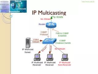
Multiple copies of the same message is transmitted on the same link Multicasting over a Packet Network • Without support for multicast at the network layer:
Multicasting over a Packet Network • With support for multicast at the network layer: • Requires a set of mechanisms: (1) Packet forwarding can send multiple copies of same packet(2) Multicast routing algorithm which builds a spanning tree (dynamically)
Semantics of IP Multicast • Multicast groups are identified by IP addresses in the range 224.0.0.0 - 239.255.255.255 (class D address) • Every host (more precisely: interface) can join and leave a multicast group dynamically • no access control • Every IP datagram send to a multicast group is transmitted to all members of the group • no security, no “floor control” • Sender does not need to be a member of the group • The IP Multicast service is unreliable
Socket Layer Stream Sockets Datagram Sockets Multicast Sockets TCP UDP IP IP Multicast The IP Protocol Stack • IP Multicasting only supports UDP as higher layer • There is no multicast TCP ! User Layer Network Interface
IP Multicasting • There are three essential components of the IP Multicast service: IP Multicast Addressing IP Group Management Multicast Routing
Multicast Addressing • All Class D addresses are multicast addresses: • Multicast addresses are dynamically assigned. • An IP datagram sent to a multicast address is forwarded to everyone who has joined the multicast group • If an application is terminated, the multicast address is (implicitly) released.
Types of Multicast addresses • The range of addresses between 224.0.0.0 and 224.0.0.255, inclusive, is reserved for the use of routing protocols and other low-level topology discovery or maintenance protocols • Multicast routers should not forward any multicast datagram with destination addresses in this range. • Examples of special and reserved Class D addresses, e.g,
Multicast Address Translation • In Ethernet MAC addresses, a multicast address is identified by setting the lowest bit of the “most left byte” Not all Ethernet cards can filter multicast addresses in hardware - Then: Filtering is done in software by device driver.
IGMP • The Internet Group Management Protocol (IGMP) is a simple protocol for the support of IP multicast. • IGMP is defined in RFC 1112. • IGMP operates on a physical network (e.g., single Ethernet Segment. • IGMP is used by multicast routers to keep track of membership in a multicast group. • Support for: • Joining a multicast group • Query membership • Send membership reports
IGMP Protocol • A host sends an IGMP report when it joins a multicast group (Note: multiple processes on a host can join. A report is sent only for the first process). • No report is sent when a process leaves a group • Changed in version 2 • A multicast router regularly multicasts an IGMP query to all hosts (group address is set to zero). • A host responds to an IGMP query with an IGMP report. • Multicast router keeps a table on the multicast groups that have joined hosts. The router only forwards a packet, if there is a host still joined. • Note: Router does not keep track which host is joined.
IGMP Packet Format • IGMP messages are only 8 bytes long • Type: 1 = sent by router, 2 = sent by host
IGMP Leave Message (in IGMP version 2) • If a host leaves a multicast group, and it was the last one to send a report, it sends a LEAVE Group message • Router follows up by a group specific query to make sure that there is indeed no other host in the group
IGMPv3 • Version 3 adds the ability to join a multicast group only for specific source addresses • Can also exclude source addresses • This permits the implementation of Source Specific Multicasting (SSM)
Only one router responds to IGMP queries (Querier) Router with smallest IP address becomes the querier on a network. One router forwards multicast packets to the network (Forwarder). Networks with multiple multicast routers
Multicast Routing Protocols • Goal: Build a spanning tree between all members of a multicast group
Multicast routing as a graph problem • Problem: Embed a tree such that all multicast group members are connected by the tree
Multicast routing as a graph problem • Problem: Embed a tree such that all multicast group members are connected by the tree • Solution 1: Shortest Path Tree or source-based treeBuild a tree that minimizes the path cost from the source to each receiver • Good tree if there is a single sender • If there are multiple senders, need one tree per sender • Easy to compute
Multicast routing as a graph problem • Problem: Embed a tree such that all multicast group members are connected by the tree • Solution 2: Minimum-Cost Tree Build a tree thatminimizes the total cost of the edges • Good solution if there are multiple senders • Very expensive to compute (not practical for more than 30 nodes)
Multicast routing in practice • Routing Protocols implement one of two approaches: • Source Based Tree: • Essentially implements Solution 1. • Builds one shortest path tree for each sender • Tree is built from receiver to the sender reverse shortest path / reverse path forwarding • Core-based Tree: • Build a single distribution tree that is shared by all senders • Does not use Solution 2 (because it is too expensive) • Selects one router as a “core” (also called “rendezvous point”) • All receivers build a shortest path to the core reverse shortest path / reverse path forwarding
Multicast Routing table • Routing table entries for source-based trees and for core-based trees are different • Source-based tree: (Source, Group) or (S, G) entry. • Core-based tree: (*, G) entry.
Reverse Path Forwarding (RPF) • RPF builds a shortest path tree in a distributed fashion by taking advantage of the unicast routing tables. • Main concept: Given the address of the root of the tree (e.g., the sending host), a router selects as its upstream neighbor in the tree the router which is the next-hop neighbor for forwarding unicast packets to the root. • This concept leads to a reverse shortest path from any router to the sending host. The union of reverse shortest paths builds a reverse shortest path tree. RPF Forwarding: Forward a packet only if it is receives from an RPF neighbor
Multicast routing in practice • Routing algorithms in practice implement one of two approaches: • Source Based Tree Tree: • Establish a reverse path to the source • Core-based Tree: • Establish a reverse path to the core router
Building a source-based tree • Set routing tables according to RPF forwarding • Flood-and-Prune
Building a source-based tree • Set routing tables according to RPF forwarding • Flood-and-Prune Flood= Forward packets that arrive on RPF interface on all non-RPF interfaces
Building a source-based tree • Set routing tables according to RPF forwarding • Flood-and-Prune Flood= Forward packets on all non-RPF interfaces Receiver drops packets not received on RPF interface
Building a source-based tree • Set routing tables according to RPF forwarding • Flood-and-Prune Prune= Send a prune message when a packet is received on a non-RPF interface or when there are no receivers downstream Prune message disables routing table entry
Pruning • Prune message temporarily disables a routing table entry • Effect: Removes a link from the multicast tree • No multicast messages are sent on a pruned link • Prune message is sent in response to a multicast packet • Question: Why is routing table only temporarily disabled? • Who sends prune messages? • A router with no group members in its local network and no connection to other routers (sent on RPF interface) • A router with no group members in its local network which has received a prune message on all non-RPF interfaces (sent on RPF interface) • A router with group members which has received a packet from a non-RPF neighbor (to non-RPF neighbor)
Building a source-based tree • When a receiver joins, one needs to re-activate a pruned routing table entry • Grafting Sending a Graft message disables prune, and re-activates routing table entry.
Alternative method for building a source-based tree • This only works if the receiver knows the source Explicit-Join • Receiver sends IGMPv3 message, where it specifies the IP address of a source • First router sends Join message to RPF neighbor • Join message creates (S,G) routing table entry • Join message is passed on until it reaches router next to source Source Specific Multicast (SSM)
Building a core-based tree • One router is the core • Receiver sends a Join message to RPF neighbor with respect to core • Join message creates (*, G) routing table entry
Building a core-based tree • Source sends data to the core • Core forwards data according to routing table entry
Multicast routing protocols in the Internet • Distance Vector Multicast Routing Protocol (DVMRP): • First multicast routing protocol • Assumes an “overlay” topology of multicast routers • Implements flood-and-prune • Multicast Open Shortest Path First (MOSPF): • Multicast extensions to OSPF. Each router calculates a shortest-path tree based on link state database • Link state advertisements for multicast groups raises scalability concerns • Core Based Tree (CBT): • First core-based tree routing protocol • Protocol Independent Multicast (PIM): • Runs in two modes: PIM Dense Mode (PIM-DM) and PIM Sparse Mode (PIM-SM). • PIM-DM builds source-based trees using flood-and-prune • PIM-SM builds core-based trees as well as source-based trees with explicit joins.
MBONE - Original Multicast Deployment • MBone (Multicast Backbone) started multicast deployment in 1992 • MBone consists of multicast routers that exchange IP multicast datagrams over a unicast IP network • DVMRP is the routing protocol for the MBone
Tunneling • MBone routers connect via IP tunnels • With tunneling, IP packets are encapsulated by another IP header (IP-in-IP encapsulation)
PIM Messages (PIM version 2) • Encapsulated in IP datagrams with protocol number 103. • PIM messages can be sent as unicast or multicast packet • 224.0.0.13 is reserved as the ALL-PIM-Routers group
PIM-DM: PIM Dense Mode • PIM-DM implements flood-and-prune • Orange packet: Multicast packet (=Data) • Blue packet: PIM message
PIM-SM: PIM Sparse Mode • Core is called rendezvous-point (RP) • Receivers know RP (statically configured or dynamically elected) • When receiver joins, a Join message is sent to RP on RPF.
PIM-SM: PIM Sparse Mode • Host H3 joins:Join message is only forwarded until the first router that is part of the core-based tree.
PIM-SM: Data transmission • Source sends multicast packet to RP • Packet is attached to an RP Register message • When packet reaches RP, it is forwarded in the tree • Also: RP sends a Join message on reverse path to S1
PIM-SM: Data transmission • When Join messages reaches R1, it sends a native multicast packet to the RP (in addition to the packet attached to the register message)
PIM-SM: Data transmission • When RP receives native multicast packet it sends a register stop message to R1. This message stops the transmission of register messages from R1.
PIM-SM: Data transmission • Resulting, one copy of data flows: • From S1 to RP • From RP to R3
PIM-SM: Switching to source-based tree • When data to receivers exceeds a threshold, routers switch to a source-based tree • This is done by sending an explicit join message to the source • There may be duplicate packets being sent for some time