Numerical Reservoir Simulation
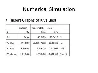
Numerical Reservoir Simulation. Next. Back. Topic Overview. An introduction to standard numerical solution techniques for reservoir flow equations. html. Back. Introduction. Gridding. Stability analyses. Differential equations for mass flow. Reservoir equations. Numerical


Numerical Reservoir Simulation
E N D
Presentation Transcript
Next Back Topic Overview • An introduction to standard numerical solution techniques for reservoir flow equations. html
Back Introduction Gridding Stability analyses Differential equations for mass flow Reservoir equations Numerical Modell Reservoir Performance Difference Approximation Discretization Error For more information click on the subject you want to learn more about.
Up Discretization Techniques • General partial differential equations for reservoir fluid flow must be discretized before they can be treated computationally. • The most common techniques are: • - finite differences • - finite elements • We will in in this module learn about the finite difference technique. html
Up Finite Differences • Finite difference approximations are used in most commercial reservoir simulation software to solve fluid flow equations numerically. • Main steps in a discretization procedure: • replace differential operators by algebraic ciexpressions • compute approximate solution at given points and iiispecified times html
Next Differential Equations for Mass Flow Mass conservation equations for Black Oil models: Where Ql are sink/source term Discretization Techniques
Next Back Reservoir Equations Discrete equations for Black Oil models for block i,j,k: For more information click on the equationyou want to learn more about. html
Up Next Water Equation The water equation consists of three parts; a flow term, a well term and an accumulation term. Flow term + well term = accumulation term For more information click on the term of the water equationyou want to learn more about. html
Up Next Flow Term for Water The flow term for water consists of three terms, one for each coordinate direction. For more information click on the term of the equationyou want to learn more about. html
Up Next Flow Term for Water in x- direction • The x-part consists of two terms; one to compute flow to neighbour block in the positive direction and one for flow in the negative direction. For information on block boundaries, click on the textbox. html
Up Back Next Flow Term for Water in y- direction • The y-part consists of two terms; one to compute flow to neighbour block in the positive direction and one for flow in the negative direction. For information on block boundaries, click on the textbox. html
Up Back Flow Term for Water in z- direction • The z-part consists of two terms; one to compute flow to neighbour block in the positive direction and one for flow in the negative direction. For information on block boundaries, click on the textbox. html
Up Back Next Well Term for Water Specification are different for production and injection wells. water Click here to see how the production term for wateris given.
Up Well Equations for Black Oil Model Pwell = pressure in the well
Up Well Equations for Black Oil Model Pwell = pressure in the well
Up Well Equations for Black Oil Model Pwell = pressure in the well
Up Back Accumulation Term for Water The change of mass of water in block i,j,k during time t between step n and n+1 is given by: html
Up Back Evaluation on Block Boundaries html
Up Back Next Oil Equation The oil equation consists of three parts; a flowterm, a well term and an accumulation term. Flow term + well term = accumulation term For more information click on the term of the oil equation you want tolearn more about. html
Up Next Flow Term for Oil The flow term for oil consists of three terms, one for each coordinate direction. For more information click on the term of the equation you want to learn more about. html
Up Next Flow Term for Oil in x- direction • The x-part consists of two terms; one to compute flow to neighbour block in the positive direction and one for flow in the negative direction. For information on block boundaries, click on the textbox. html
Up Back Next Flow Term for Oil in y- direction • The y-part consists of two terms; one to compute flow to neighbour block in the positive direction and one for flow in the negative direction. For information on block boundaries, click on the textbox. html
Up Back Flow Term for Oil in z- direction • The z-part consists of two terms; one to compute flow to neighbour block in the positive direction and one for flow in the negative direction. For information on block boundaries, click on the textbox. html
Up Back Next Well Term for Oil Specification are different for production and injection wells. oil Click here to see how the production term for oilis given.
Up Back Accumulation Term for Oil The change of mass of water in block i,j,k during time t between step n and n+1 is given by: html
Up Back Gas Equation The gas equation consists of a flow term for gas and dissolved gas, a well term and an accumulation term for gas and dissolved gas. Flow terms+ well term = accumulation terms For more information click on the term of the equation you want to learn more about. html
Up Next Flow Term for Gas The flow term for gasconsists of three terms, one for each coordinate direction. For more information click on the term of the equation you want to learn more about. html
Up Next Flow Term for Gas in x- direction • The x-part consists of two terms; one to compute flow to neighbour block in the positive direction and one for flow in the negative direction. For information on block boundaries, click on the textbox. html
Up Back Next Flow Term for Gas in y- direction • The y-part consists of two terms; one to compute flow to neighbour block in the positive direction and one for flow in the negative direction. For information on block boundaries, click on the textbox. (not active yet) html
Up Back Flow Term for Gas in z- direction • The x-part consists of two terms; one to compute flow to neighbour block in the positive direction and one for flow in the negative direction. For information on block boundaries, click on the textbox. html
Up Back Next Flow Term for Dissolved Gas The flow term for dissolved gasconsists of three terms, one for each coordinate direction. For more information click on the term of the equation you want to learn more about. html
Up Next Flow Term for Dissolved Gas in x- direction • The x-part consists of two terms; one to compute flow to neighbour block in the positive direction and one for flow in the negative direction. For information on block boundaries, click on the textbox. html
Up Back Next Flow Term for Dissolved Gas in y- direction • The y-part consists of two terms; one to compute flow to neighbour block in the positive direction and one for flow in the negative direction. For information on block boundaries, click on the textbox. html
Up Back Flow Term for Dissolved Gas in z- direction • The z-part consists of two terms; one to compute flow to neighbour block in the positive direction and one for flow in the negative direction. For information on block boundaries, click on the textbox. html
Up Back Next Well Term for Gas Specification are different for production and injection wells. gas Click here to see how the production term for gasis given.
Up Back Accumulation Term for Gas and Dissolved Gas The change of mass of water in block i,j,k during time t between step n and n+1 is given by: html
l = o,w,g s = x,y,z p = i,j,k ql,i,j,k = Ql,i,j,k = = Sl = Bl = [k] = k = l = Vi,j,k = t = t = Rs = Rs = sTls = sls = WIp = pi = pwell = Back Definition of Symbols
Next Back Difference Approximations Taylor series can be used to derive a difference formula for single and double derivates. Taylor series of f(x+x) and f(x-x) are given by: With these expansion we can deduce: - first order approximation of f’ - second order approximation of f’ - second order approximation of f’’ html
Up Next First Order Approximation of f’ From the expansion of f(x+Δx) we get an expression for f’(x): From the expansion of f(x-Δx) we get an expression for f’(x): This difference formula is used for discretizing time derivative in the mass equations Click on the box to see how the approximation changes when the step size is halved. html
Up Difference Formula A first order approximation of ut at the point n+1 is given by: The time axis is divided into points at distance Δt: html
Back First Order Approximation of f’ From the serie f(x+Δx): From the serie f(x-Δx): The step size reduction produces more accurate approximations. html
Up Next Back Second Order Approximation of f’ Adding expansion of f(x+Δx) and f(x-Δx) results in the approximations: html Click on the box to see how the approximation changes when the timestep is halved.
Up Back Second Order Approximation of f’ The sum of f’(x) of the series f(x+Δx) and f(x-Δx): Step size reduction will produce more accurate approximations. html
Up Back Second Order Approximation of f’’ The sum of the Taylor series f(x+Δx) and f(x-Δx) is used to deduced a second order approximation of f’’: This approximation is frequently used and the numerator is written: html
Back Difference Approximation Uxx can be approximated at each point i by the formula: html
Next Back Discretization Error The order of a difference approximation can by analysed using Taylor expansions. The discretization error approaches zero faster for a high order approximation then for a low order approximation. html
Next Back Gridding A faulted reservoir Well locations An imposed grid Initial fluid distribution Click to the picture for sound (not active yet) html
Up Next A Faulted Reservoir (Not active yet)
Up Next Back Well Locations (Not active yet)
Up An Imposed Grid Main criteria for grid selection: • The ability to identify saturations and pressures ii at specific locations (existing and planned well i iiiilocations). • The ability to produce a solution with the i iiiirequired accuracy (numerical dispersion and iiiigridorientation effects). • The ability to represent geometry, geology and iiiphysical properties of the reservoir (external iiiboundaries, faults, permeability distribution iiiincluding vertical layering). • Keep the number of grid blocks small in order to iiimeet requirements of limited money and time iiiavailable for the study.