
Construct the Hot Wire Foam Cutter
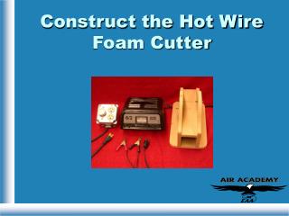
Construct the Hot Wire Foam Cutter. Needed Parts. Junction box UL-approved 16/3 cord with grounded plug Outlet Dimmer switch 6/12V battery charger with 6A output Wire Hardware 5/8” particle board. Guidelines.

Construct the Hot Wire Foam Cutter
E N D
Presentation Transcript
Needed Parts • Junction box • UL-approved 16/3 cord with grounded plug • Outlet • Dimmer switch • 6/12V battery charger with 6A output • Wire • Hardware • 5/8” particle board
Guidelines • Only people experienced in shop safety practices should attempt this procedure. • Take precautions to ensure the completed project is safe for use.
Procedure • Mount outlet and dimmer switch to top of junction box. • Install strain relief clamp onto junction box and route cord leadsinto box.
Procedure 3. Connect leads as follows:splice cord white to lead from dimmer, cord black to terminal on side of outlet labeled black, cord green to gnd terminal on outlet. Connect remaining dimmer lead to terminal on side of outlet labeled white Connect gnd lead between dimmer gnd and outlet gnd. 4. Assemble box.
Procedure Route forcrosspiece • Use 5/8” particle board for wire mount. Base is 7” x 12”. Crosspiece is 3-1/4” X 12”. Sides are cut from rectangles 7” x 12”. Cut tops of sides as shown (curve starts 4-1/4” from bottom edge). Route sides for crosspiece, top of route 3-1/4” from top of side. Route base for sides. All routes ¼” deep. Glue crosspiece and sides into routed slots. Route for sides
Procedure 6. Drill holes to allow 2” clearance between wire and crosspiece. Single bolt held in place with nuts, has hole through shaft to insert wire through, wire then wrapped around shaft. Opposite bolt has hole length of shaft, wire fed through shaft, out head, wrapped around screw mounted below bolt. 2”
Procedure 7. Attach clamps from battery charger to screw/terminals on wire cutter as shown. Use 6V, 6A settings on charger, rotate dimmer to read 4A on meter. Plug charger into control box.


![11 Free Video Cutter Software List [Hot]](https://cdn5.slideserve.com/10105179/11-free-video-cutter-software-review-dt.jpg)