Download

1 / 80
800 likes | 1.07k Vues
Mechanics of Materials II. UET, Taxila Lecture No. (4&5). Mechanisms of material failure. In order to understand the various approaches to modeling fracture, fatigue and failure, it is helpful to review briefly the features and mechanisms of failure in solids. Failure under monotonic loading.

E N D
Mechanics of Materials II UET, Taxila Lecture No. (4&5)
Mechanisms of material failure In order to understand the various approaches to modeling fracture, fatigue and failure, it is helpful to review briefly the features and mechanisms of failure in solids.
Failure under monotonic loading If you test a sample of any material under uni-axial tension it will eventually fail. The features of the failure depend on several factors, including:
1-The materials involved and their micro-sctructure 2-The applied stress state 3- Loading rate 4-Temperature 5-Ambient environment (water vapor; or presence of corrosive environments)
Materials are normally classified loosely as either `brittle’ or `ductile’ depending on the characteristic features of the failure. Brittle and Ductile failures
Brittle Materials Examples of `brittle’ materials include: glasses, ceramics (Oxides, Carbides & Nitrides) and Cast Iron
Features of a brittle material are 1-Very little plastic flow occurs in the specimen prior to failure; 2-The two sides of the fracture surface fit together very well after failure.
3- The fracture surface appears faceted – you can make out individual grains and atomic planes. 4- In many materials, fracture occurs along certain crystallographic planes. In other materials, fracture occurs along grain boundaries
Ductile Materials Examples of `ductile’ Tin and lead FCC metals at all temperatures; BCC metals at high temperatures; polymers at relatively high temperature.
Features of a `ductile’ fracture are Extensive plastic flow occurs in the material prior to fracture. There is usually evidence of considerable necking in the specimen
Fracture surfaces don’t fit together. The fracture surface has a dimpled appearance – you can see little holes
Complex Materials Of course, some materials have such a complex microstructure (especially composites) that it’s hard to classify them as entirely brittle or entirely ductile.
How Brittle Fracture occurs Brittle fracture occurs as a result of a single crack, propagating through the specimen. Most materials contain pre-existing cracks, in which case fracture is initiated when a large crack in a region of high tensile stress starts to grow.
How ductile fracture occurs Ductile fracture occurs as a result of the nucleation, growth and coalescence of voids in the material Failure is controlled by the rate of nucleation of the voids and their rate of growth.
Does material fail under stresses lower than yield strength?
This chapter would not be complete, therefore, without reference to certain loading conditions under which materials can fail at stresses much less than the yield stress, namely creep and fatigue.
Creep and Fatigue In the preceding sections it has been suggested that failure of materials occurs when the ultimate strengths have been exceeded.
Definition of creep Creep is the gradual increase of plastic strain in a material with time at constant load.
Creep at high temperature At elevated temperaturessome materials (most metals) are susceptible to this phenomenon and even under the constant load mentioned, strains can increase continually until fracture.
Applications of creep This form of fracture is particularly relevant to turbine blades, nuclear reactors, furnaces, rocket motors, etc.
In previous figure: The general form of the strain versus time graph or creep curveis shown for two typical operating conditions.
Four features In each case the curve can be considered to exhibit four principal features:
(a) An initial strain, due to the initial application of load. In most cases this would be an elastic strain. (b) A primary creepregion, during which the creep rate (slope of the graph) diminishes.
(c) A secondary creep region, when the creep rate is sensibly low (Constant). (d) A tertiary creep region, during which the creep rate accelerates to final fracture.
Design for creep It is clearly vital that a material which is susceptible to creep effectsshould only be subjected to stresses which keep it in the secondary (straight line) region throughout its service life.
This enables the amount of creep extension to be estimated and allowed in design.
Fatigue Definition of Fatigue Fatigueis the failure of a material under fluctuating stresses each of which is believed to produce minute amounts of plastic strain.
Applications of fatigue Fatigue is particularly important in components subjected to repeated and often rapid loadfluctuations, e.g. aircraft components, turbine blades, vehicle suspensions, etc.
Representation of Fatigue Fatigue behaviour of materials is usually described by a fatigue life or S-N curve in which the number of stress cycles N to produce failure is plotted against S.
Fatigue limit The particularly relevant feature of this curve is the limiting stress Snsince it is assumed that stresses below this value will not produce fatigue failure however many cycles are applied, i.e. there is infinite life.
Design for fatigue In the simplest design cases, therefore, there is an aim to keep all stresses below this limiting level.
Solved Examples
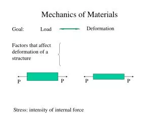
Example 1 Determine the stress in each section of the bar shown in next Figure when subjected to an axial tensile load of 20 kN. The central section is 30 mm square cross-section; the other portions are of circular section, their diameters being indicated. What will be the total extension of the bar? For the bar material E = 210GN/m2.
Now the extension of a bar can always be written in terms of the stress in the bar since