MaPMT L0 Electronics & Photo detector mounts
MaPMT L0 Electronics & Photo detector mounts. Report from meeting at CERN 22 May 2003 and follow-ups L0 motherboard Design completion scheduled for end 2003 on critical path for MaPMTs Photo detector mounts

MaPMT L0 Electronics & Photo detector mounts
E N D
Presentation Transcript
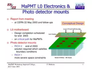
MaPMT L0 Electronics &Photo detector mounts • Report from meeting • at CERN 22 May 2003 and follow-ups • L0 motherboard • Design completion scheduled for end 2003 • on critical path for MaPMTs • Photo detector mounts • RICH 2 end of 2003 solution required which satisfies boundary conditions • RICH 1 more severe space constraints Conceptual Design F. Muheim
3 x 3 MaPMT Cluster Set-up 40 MHz Read-out APVm chip F. Muheim
Bleederboards F. Muheim
MaPMT Module • Modules of 4x4 MaPMTs • 16 tubes, 1024 channels • Size: 113.8 x 113.8 mm2 • Filling factor: 0.72 • Frame: carbon fibre, G10 • Cooling: 16 W / module • -metal shield • for individual tubes 0.9 mm thick • Lenses • incorporated in module • no optical contact • RICH system • # of modules: 232 • 3504 MaPMTs • # of channels: 237 kc Proposal for photodetector choice / TDR F. Muheim
LHCb RICH2 MaPMTs F. Muheim
Cooling • Power Dissipation • Bleeder board 0.55 W / resistor chain at HV = 1000 V • Power dissipation 8.8 W / module (MaPMTs) 2.2 W / module if 4 tubes share resistor chain • Beetle chip 750 to 900 mW or 6-7 mW / channel • Power consumption 7.2 W / module (8 Beetle chips) • Total power dissipation 16 W / module~ 1000 W/ half plane • compare EUSO200 W / plane need to understand this difference • Cockroft-Walton • Cooling design • needs input from L0 motherboard design Connections, Beetle pad layout F. Muheim
RICH2 Photo Detector Plane • Proposal by Olav • Assumptions • basic unit for electronics 1024 channels, 8 Beetles, 16 tubes • From cooling simulationsheat sink not more than 2 tubes wide • Modules of 8 x 2 MaPMTs • MaPMT pitch 28 mm • module width 56 mm • module height 224 mm • RICH 2 implementation • # of modules 72 / half plane • # of MaPMTs 1152 / half plane F. Muheim
Photo Detector Footprint • Assumptions • MaPMT pitch 28.45 mm (Olav used 28 mm) • RICH 2 half plane • photo detector area 1300 mm x 682 mm (RICH2 EDR) • 6 columns with 11 modules of 4x4 tubes, total 1056 MaPMTs 12 columns with 6 modules of 2x8 tubes, total 1152 MaPMTs • RICH 1 half plane • photo detector area 1200 mm x 540 mm (email Dave Websdale) • 11 rows with 5 modules of 4x4 tubes, total 880 MaPMTs 6 rows with 10 modules of 2x8 tubes, total 960 MaPMTs • Total RICH 1 and RICH 2 • # of MaPMTs with 4x4 modules 3872 • # of MaPMTs with 8x2 modules 4224 • less flexibility with 8x2 modules up to 9% more MaPMTs and electronics needed F. Muheim
Magnetic Shield/Lenses • -metal shield • for individual tubes • thickness: 0.9 mm increased B field in RICH 1 • not necessary in RICH 2 • Lenses • could be incorporated in magnetic shielding F. Muheim
Magnetic Shields • Magnetic Field Measurements • documented in note LHCb 2003-042 • requirement 10% maximum loss of photons • MaPMT needs shielding above 20 G longitudinal field • with -metal shielding can operate up to 80 G • RICH 2 • maximum B-field in box 4.1 … 9.1 G (RICH2 EDR) • about 5% loss of photo electrons at 10 G • safety factor >2 for <10% loss requirement • -metal shielding not required for RICH 2 • RICH 1 • see talk by Bill Cameron F. Muheim
MAPMT 0.9 13 Longitudinal B-Field -metal shielding: 0.9 mm thick 13 or 20 mm extension 90% shielded MaPMT with 13 mm extension: MaPMT functions in longitudinal fields up to 8 mT (80 G) F. Muheim
Lenses & m-metal Design • Different mounting designs possible • Lenses / -metal mounted onto modules (Geoff Barber et al) • lenses glued to MaPMT or spring loaded • easy to exchange, little clearance needed • costs if lenses are not glued to MaPMT • lenses glued to MaPMT, transparency of glue • Lenses / -metal separate structure from modules • lenses or lens-arrays glued together • can be used as gas seal, cost savings, no more quartz window • cost savings, structure is glued • larger clearance wrt to MaPMTs, seal must be gas tight • cannot replace lens if it breaks or turns yellow • Lenses are separate structure from -metal • -metal can be part of modules • can combine advantages of above 2 designs • cost, complexity likely increases F. Muheim
Transparent Glue • EPO-TEK 301-2 • 2 component epoxy • refractive index 1.564 • increased B field in RICH 1 • not necessary in RICH 2 • Transmission • > 97% from 300 nm .. 2.5 m • Needs study • Is EUSO using it? F. Muheim
Issues • Footprints of RICH2 and RICH2 • agree on dimensions for basic componentsurgent • 4x4 vs 8x2 decision when? • Magnetic Shields • RICH 2 no -metal shields ok • RICH 1 Is -metal shield really needed when? • Lenses • study moulded lenses • agree on dimensions could be different for RICH 1 and RICH 2 when? • Decide if lenses make gas seal soon • Photo detector mounts • decide on design of lenses / -metal when? • Next steps • Produce plan with decision points F. Muheim
Backup Slides F. Muheim
MaPMTL0 motherboard MaPMT meeting CERN 22 May 2004 Franz Muheim University of Edinburgh on behalf of MaPMT group
L0 Interface Board 1st prototype GOLs VCSEL JTAG connector Power supply regulators PINT DACs connectors to PIXEL chip F. Muheim TTCrx on reverse of board…
Reverse of L0 Interface Board 1st prototype TTC receiver chip TTCrx F. Muheim
Transverse B-Field Transverse field in x-direction 90% MaPMT insensitive to transverse fields up to 23mT (230 G) without shielding normalised light yield in whole MaPMT F. Muheim
R1 R5 R6 C1 C6 Longitudinal B-Field No shielding • Colour • Legend • 1 mT • 2 mT • 3 mT • 4 mT • 5 mT • 6 mT • 7 mT • 8 mT • 9 mT • 10 mT • 15 mT • 20 mT • 25 mT • 30 mT • 35 mT light yield: rows light yield: columns 6mT Conclusions: Agreement with previous test Top and bottom row drop first Sizable loss for edge rows at 3mT Decrease due to loss of p.e. Row 5 anomaly understood from x-talk in APVm readout CoG: rows CoG: columns F. Muheim