Enhanced Loran
Enhanced Loran. Sherman Lo, Benjamin Peterson With contributions from the FAA Loran Evaluation Team. Acknowledgments & Disclaimer. The presenters gratefully acknowledge the Federal Aviation Administration (FAA) Loran evaluation team and Mitchell Narins

Enhanced Loran
E N D
Presentation Transcript
Enhanced Loran Sherman Lo, Benjamin Peterson With contributions from the FAA Loran Evaluation Team
Acknowledgments & Disclaimer • The presenters gratefully acknowledge the Federal Aviation Administration (FAA) Loran evaluation team and Mitchell Narins • The views expressed herein are those of the authors and are not to be construed as official or reflecting the views of the U.S. Coast Guard, Federal Aviation Administration, Department of Transportation or Department of Homeland Security or any other person or organization.
Executive Summary • Enhanced Loran designed to provide back up/redundancy to GPS/GNSS in safety critical applications • Aviation, Maritime, Precise Time • Loran for tactical purposes is possible with efficient transmitters • Loran is difficult, but not impossible to spoof/jam • Loran future still uncertain
Outline • General Overview of Loran • System & operations • Status • Complement to GNSS in civil critical infrastructure • Aviation, Maritime, Timing • Tactical Loran • Loran & Jamming/Spoofing
Loran History • The first all weather continuous operating long range navigation system • Pulsed transmission, “TDMA” • Operational 1958, operated by USCG • Accuracy ~ 0.25 to 1 mile Repeatable ~ 18-90 m • Horizontal navigation • Enjoyed widespread use for maritime navigation • 625’+ tall towers at 400+ kW
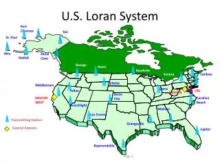
Loran Coverage Worldwide Courtesy: Megapulse
Repetition Interval for Chain B CHAIN B Master Station X Station Y Master Station X Master Station W Station X Station Y Master Station W Repetition Interval for Chain A Time LORAN Chain Timeline CHAIN A • Other Loran chains can cause interference on desired Loran signals
Master Station W Station X Station Y Master Station X Repetition Interval for Chain A (GRI 9940) Time Getting Time Differences from Loran TDOAMY+NEDY TDOAMX+NEDX TDOAMW+NEDW • NED is the transmission delay from the master • Absolute time, TOT control, allows for true pseudoranges
Loran Envelope Zoom of Loran GRI
Major sources of uncertainty • Noise • Thermal & atmospheric noise • Precipitation static • Transmitter jitter (100-500 ns limit) • Variation of propagation delay • Distance dependent (severe case: 500 m peak to peak) • Generally slowly varying in time • Interference (often mitigated by processing) • Skywave • Crossrate • CW & RFI • Reradiation • Large metallic elements (i.e. bridges) • Distortion about buildings
Noise Thermal & atmospheric noise Precipitation static Transmitter jitter (100-500 ns limit) Variation of propagation delay Distance dependent (severe case: 500 m peak to peak) Generally slowly varying in time Interference (often mitigated by processing) Skywave Crossrate CW & RFI Reradiation Large metallic elements (i.e. bridges) Distortion about buildings Major sources of uncertainty
Temporal ASF Variations • As weather changes, properties such as terrain conductivity, permittivity, moisture level changes • Results in different propagation speeds and variations in the delay on the pulse • Phase delay (ASF) and ECD varies in time
Enhanced Loran (eLoran) • Next generation of Loran • Provides changes to improve accuracy, reliability, integrity, availability • Governmental Policy changes (prop. delay (ASF) tables) • Operational changes (TOT control) • Transmitter equipment (control, Cs clock, etc,) • Data Channel (integrity, dLoran, timing) • User equipment (All in view receiver, H field antenna) • These changes are or are being implemented
Loran Status • The Presidental DHS budget (Feb 2009): • “supports the termination of outdated systems such as the terrestrial-based, long-range radionavigation (LORAN-C) operated by the U.S.Coast Guard resulting in an offset of $36 million in 2010 and $190 million over five years.” • No mention of eLoran is made (however eLoran needs Loran-C infrastructure) • Federal Radionavigation Plan (Feb 2009) eLoran suggested as possible GPS back up • Congressional stance uncertain • Some current language indicates support for keeping Loran ($ 37 M budgeted for operations & upgrade) • Bottomline: Loran future is uncertain
eLoran Receiver Manufacturers Timing Receivers Navigation Receivers
GPS/WAAS/eLoran Receivers for Maritime Signal Processor77 x 51 mm Front End & ADC77 x 47 mm GPS – WAAS 85 mm 110 mm 30 mm
Analog Board DSP Loran Interface Board Rubidium Main Board Single Board Computer Power Supply Enhanced Loran Receiver Front Back Courtesy: Kirk Montgomery, Symmetricom
Transmitter Manufacturers • Megapulse • Built the current Loran solid state transmitters (SSX) • Based on tuned circuit - half cycle generators (HCG) • SSX use 16 to 32 HCG • Nautel • Prototype efficient, low cost Loran transmitter in 2007-8 • amplifier & combiner section • Efficient power recovery • Based on broadcast FM/AM, etc. amplifier technology
Why have Loran and GNSS • Relying more and more on GNSS for safety & economic infrastructure • Timing for cell tower, shipping, aviation, etc. • Concerns about outage or unavailability of GNSS • reduce operational capability • Loran has dissimilar characteristics • Signal power, frequency, characteristics • Failure modes independent from GNSS • Loran has similar outputs • RNAV (lat,lon, time) - seamless to user • Could provide similar operational capabilities
Primary Areas of Interest • Aviation • Enroute (RNP 1.0 type procedures)* • Terminal & Approach (NPA, LNAV, RNP 0.3) • Others? (Surveillance (ADS-B)) • Maritime • Ocean & Coastal Confluence Zone* • Harbor Entrance Approach (HEA) • Timing & Frequency • < 50 ns timing accuracy (USNO) • Stratum 1 frequency source (10-11)* * Available with Loran-C
Loran vs. eLoran: Technical differences • Data channel • Time of transmission control • All stations synchronized to UTC, hence easier ranging • Position domain errors generally lower • SAM control minimize error at 1 locale • Transmitter clock • Improved clocks (already installed) • Improved algorithms/control loops • Tighter tolerances
Enhanced Loran - Loran Data Channel • Pulse position modulation on Loran signal • 18.8 to 31.6 baud per channel, up to 4 channels on dual rated station • Time of Day, Leap Seconds • Differential Loran corrections for temporal variations in phase • Improves accuracy for harbor entrance to 10 m (95%) • Requires harbor survey for spatial variations • Comparable improvement in timing accuracy • Stanford developing authentication methodology • Authentication messages transmitted from Middletown, CA
Current Loran Data Channel Coverage(Time of Day only except Seneca & Middletown) Authentication(Stanford) Differential Corrections
Differential Loran Map Spatial ASF Differences TOA ASF (TOA) Variation
Enhanced Loran – GPS Independence Currently 5071 Cesiums steered using GPS If GPS lost, coasts for a few weeks on Cesiums, then UTC sync maintained using Loran signals (as is done in Europe & Russia) LSU investigating alternative to GPS for primary source of UTC Including but not limited to TWSTT Final solution is Kalman filter using TWSTT (or equivalent), GPS, & Loran Sub-nanosecond level not needed for Loran but paper clock of 87 5071’s; 3 each 29 remote sites compared at this level is national asset
Enhanced Loran Timing Receiver IRIG-B LORAN GPS
Time/Frequency Recovery Courtesy: Kirk Montgomery, Symmetricom
Elsis Tracker Other Benefits • Indoors & urban canyon • GNSS/Loran integration • Capability of reaching some places that are difficult for GNSS • Static Heading • Can use dual loop antenna to get heading • Authentication/Secure location • Authentication message tested • Many properties useful for location based security
Efficient, Low Power Transmitters Enables Tactical Loran • Fixed tactical Loran transmitters • Improve coverage for areas with Loran • Use existing assets w. shorter antennas • Loran mini chain for tactical purposes • Areas with no or inadequate Loran coverage • Loran on Mobile Platform • Possibilities include: Aerostats, Airships, Fixed wing aircraft, Large navigational buoys, Offshore platforms
Mobile Loran • Key issue: phase center errors for moving or tethered transmitters • Removed by differential corrections • Requires • Fixed base separate from transmitter • Moderate aircraft dynamics
Radiation Power Vtop = 0 • Short Monopole • Voltage zero at end and maximum at base • Limit is often this voltage differential (Max V) • Reactance mostly capacitative • Resistance • Loss components (Rloss) • Radiative component (Rr) • Radiated Power • Current flow • Radiative Resistance (Rr) Short Monopole Model Z = R+j*X Imax = Vmax/|Z| P = I2Rr Vbase
Simple Model of Antenna Performance • Radiation resistance for a short monopole & simple TLM over a ground plane • Short antenna – reactance is essentially capacitative • Typical US Loran transmitter has 190 m TLM, slightly over 2 ohms, 700 amps peak current for 400 kW peak power • Short antenna are high Q • Narrow band, significant energy is stored
Compatible Loran Signal • Standard Loran signal may not be best • Shorter range = less skywave • Skywave a prime driver of Loran signal design • Design signal with longer rise time and more dwell time at peak amplitude (narrower BW, more efficient) • Higher duty cycle also possible • More pulses for given time window • Increased number of pulses per GRI (if it can be accommodated) • Longer time window • Constraints • Spectrum • Transmitter limits on signal output, pulse/sec • Skywave
Antenna Current Amplitude microseconds BPSK-Raised Cosine Signal • Example: 6.25 kHz BPSK x Raised Cosine • Phase shift in nulls • Easier for tx • 20.48 ms in length • 128 pulses • Vs. 8-10 ms (1 pulse/ms) Loran
Spectrum dB re peak Autocorrelation Unfiltered Filtered microseconds microseconds Spectrum & Autocorrelation of BPSK Raised Cosine Design • Unfiltered & 16 kHz filtered BPSK designs • Both designs within spectrum • 99.7%, 99.9% • Reasonable autocorrelation for navigation • similar to Loran • Reasonable for transmission equip to output
Nominal Performance of BPSK-RC vs. Loran Tracking 52 μsec from peak -150 -100 -50 0 50 Delay from peak (μsec) Accounts for transmission length difference 20.48 ms (BPSK) vs 8 ms (Loran)
120 75 110 70 100 65 90 60 80 dB re 1 μ V/m fro 100 kW peak power 70 55 60 50 50 45 40 30 40 200 200 300 300 400 400 500 500 600 600 700 700 800 800 900 900 1000 1000 12.5 kW peak – 100 kW Equivalent Loran 1.25 kW peak – 10 kW Equivalent Loran Skywave & Groundwave Amplitudes Skywave Delay Skywave delay in μsec Range to Transmitter (km) Range to Transmitter (km)
Skywave Assessment 12.5 kW peak – 100 kW Equivalent Loran 1.25 kW peak – 10 kW Equivalent Loran Range 800 km 500 km Daytime Skywave delay 42 us 55 us Skywave/Groundwave (SGR) +3 dB -10 dB Nighttime Skywave delay 68 us 92 us Skywave/Groundwave +10 dB -1 dB (Assuming 3mmhos/m & sig strength of 50 dB re 1 uv/m) May want to limit range so that SGR < ~3 dB
Loran and Secure Navigation • Claim: Loran has properties that can be used navigation robustness against spoofing and jamming • Obvious benefits in GNSS jamming • Examine claim of robustness for various attacks • On air (Physical defense, Signal checks) • Off air • Direct injection (Authentication) • Rebroadcast injection (Cross check, Hidden information)
On Air Attack: Jamming & Spoofing Z Y M X M X Y Z User Adversary transmits signal to compete with actual broadcast
Typical Loran Field Strength (100 kW transmission) S. Lo & P. Enge, "Analysis of the Enhanced LORAN Data Channel", 2nd Int’l Symp. on Integrate LORAN-C/Eurofix & EGNOS/Galileo, Bonn, Germany, Feb. 2001 Loran Field Strength & Received Power ~ 1/r2