Images, Textures, and Vision
600 likes | 781 Vues
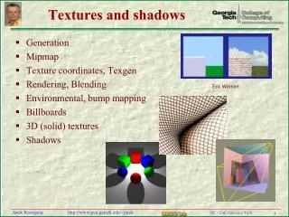
Images, Textures, and Vision. What are the issues as related to MR/VR?. Textures, billboards, sprites Image based rendering Image interpolation Image warping Distortion correction 3D vision / Reconstruction Image based objects Interaction Tracking Gesture/Object recognition?

Images, Textures, and Vision
E N D
Presentation Transcript
What are the issues as related to MR/VR? • Textures, billboards, sprites • Image based rendering • Image interpolation • Image warping • Distortion correction • 3D vision / Reconstruction • Image based objects • Interaction • Tracking • Gesture/Object recognition? • Image mixing / composition • Registration (Augmented Reality) • Non photorealistic rendering • Image analysis and processing
Using Images in Modeling: Texturing Modeling with polygons vs. Creative use of Textures (http://www.siggraph.org/education/materials/HyperGraph/mapping/r_wolfe/r_wolfe_mapping_9.htm)
Sampling Theory • Insights into the problems with images (and image based approaches) which is “sampled” from reality by some device • Aliasing • Reconstruction (Interpolation) • Resampling
Sampling system / Post-processing Original Image Transform(Correction, Morph, IP, etc) Sampling Immediate New Output Reconstruct/Resample (Anti-aliasing, …) Output (Digitized) New Output
Image sampling • Acquisition (by some device) • Digitization and Quantization • Image as array of intensity (color) values • Digital image processing (in spatial domain for now) • Thresholding (e.g. contrast stretching) • Histogram (e.g. contrast equalization) • Image subtraction (e.g. extract the changed portion) • Averaging (e.g. noise removal with large sample images) • Spatial filteringR = ω(-1, -1) f (x-1, y-1) + ω(-1, 0)f(x-1, y) +…+ ω(1,1)f(x+1, y+1)(weighted sum of neighborhood image values) • Blurring • Sharpening
R = ω(-1, -1) f (x-1, y-1) + ω(-1, 0)f(x-1, y) +…+ ω(1,1)f(x+1, y+1) Smoothing / Averaging
Sharpening ▼2f(x,y) = f(x+1,y) + f(x-1,y) + f(x,y+1) + f(x, y-1) – 4f(x,y) g(x,y) = f(x,y) - ▼2f(x,y)
Let’s get a little deeper (frequency domain) • Fourier Transform: represent the signal (image) with weighted sum of sines and cosines • 1D Discrete FT Formula F(u) = 1/M ΣM-1x=0 f(x) e-j2πux/M • 2D Discrete FT FormulaF(u, v) = 1/MN ΣM-1x=0ΣN-1y=0 f(x, y) e-j2π(ux/M + vy/N)
Image as represented in Freq. domain • Hard to visualize • u, v are indices into frequencies for sines and cosines components (nothing to do with spatial layout) • Frequency: Rate of change of intensity variation • Slowest varying frequency (u = v = 0): Ave. intensity • In the spatial region, e.g. • Walls: Low freq. region • Edges: Med/high freq. region • Noises: Highest freq. region
Digitized output as result of filtering • Filter: System that processes input signal, f(x), to produce a response g(x) • Assume linear filter • Proportional to input • αf(x) α g(x) • f1(x) + f2(x) g1(x) + g2(x) • Space invariant • f(x-a) g(x-a) Original Image Sampling Filter Output (Digitized)
Impulse / Impulse response 1 • Impulse • Delta function: δ(x) • δ(x) = 1, when x = 0 • δ(x) = 0, everywhere else • Impulse response: how filter responses to impulse • From impulse response, we can figure out properties of the filter (how it responses to general signal) • Poles and zeros • Stability 0 0
Convolution • Multiplying in frequency domain • H (u, v) • F(u, v) = G(u, v) • Convolution is commutative! • What is the counter part in the spatial domain? • H (u, v) • F(u, v) = H(x, y) * F(x, y)= 1/MN ΣM-1m=0ΣN-1n=0 h(m, n) f(x-m, y-n) • Weighted sum of neighborhood pixels
Back to sampling • Input: Original continuous image • Sampling Filter function: Delta function • Convolution of function with impulse copies value of that function at that location (sifting property) • 1/MN ΣM-1m=0ΣN-1n=0 s(x, y) Aδ(x-x0, y-y0) = A s (x0, y0) (Aδ(x-x0, y-y0) = 0 except at x0, y0) • Output: Sampled image(for final digitization, do quantization)
Reconstruction • What if digitized output and display resolution is not the same? • If display has relatively larger resolution (like in zooming in) • Fill in the hole (interpolate) • If display has relatively lower resolution(like in zooming out) • Consolidate neighborhood?
Potential problem: Under-sampling • Sampling must be done at rate (# of samples per unit distance) equal or greater than twice the highest frequency of the original signal • If not, “aliasing” problem will occur when signal is “reconstructed” • Related problem: Zooming • Reconstruction needed again
Back to Reconstruction (filling in the hole) • Spatial domain • Nearest neighbor (pick one) • Bilinear interpolation? = ax + by + cxy + da, b, c, d from four knowns • Frequency domain • Convolution • Convolving with rectangular= Nearest neighbor • Convolving with triangular= Linear interpolation in spatial • Convolving with Gaussian
Nearest Neighbor • f(x) = f(xk), (xk-1+ xk) / 2 < x <= (xk+ xk+1)/ 2 4 5 6 7 4.8 1 0.5 -0.5
1 -1 1 Linear Interpolation • f0 + (x-x0 / x1- x0) (f1 – f0) f1 ? f0 x0 x x1
Further practical problems • When sampling, the delta functions are not perfect • When sampling and doing convolution it is done within limited frequency band (rather than + - infinity) • Frequency response of output image is different from original (not band limited) • Some garbage frequency components appear repeatedly • Apply low pass filter to remove that component before doing the reconstruction
Garbage / Artifacts • Frequency response of digitized output should look like (ideally) But looks like,
Resampling • Adapting reconstructed image to output display • If I have reconstructed image (interpolated image) as a functional, then sample at appropriate places (on the image grid, for instance) • Or apply reconstruction interpolation at resampling position
Pasting Textures: The Behind story • Scan Conversion first (Let’s take a triangle for example) • 3 vertices (with color) are projected on to screen (triangle has a normal) • On screen space, we figure out the boundaries of the triangle and scan from left to right and figure out the color for each pixel on the screen using light shading equation (e.g. using color at each vertex, normal direction and light direction)
Texturing is similar • We first associate three 3D vertices with three points in the texture (rectangular) • As we scan convert, we map the triangle region in texture space to triangle on screen space Figure out what “texel” to paste at a given pixel during scan conversion • Many different mapping is possible: u, v U, V • Planar: Linear, Bilinear, Projective • Cylindrical • Rectangular map • Spherical • Reflection • Bump
1. Three corresponding points between triangle vertices and region in texture 2. Projection on to display screen 3. Scan conversion 3.1 Map the right texel from texture through parameterization
(U, V) (u, v) (u, v) (U, V)
Parameterization of each space • Source: (u, v), 0 ≤ u, v ≤ 1 • Destination: (U, V), 0 ≤ u, v ≤ 1 • Triangle: P0 + P1 * u + P2 * v • Quadriliteral: (u, v) = f(P1, P2, P3, P4) • Surface Parameterization
(U, V) (u, v) Triangle to triangle Target triangle 에서 U, V 로 Texture space 해당하는 것을 찾는다 Given point on target triangle = A + U (C- A) + V (B – A) (barycentric representation, target triangle vertices A, B, C) u = a1 x + b1 y + c1 v = a2 x + b2 y + c2 Coefficient comes solving equation with 3 corresponding pts Substitute u, v value into barycentric representation of texture triangle
Linear Mapping • Input: u, v • Mapping Relationship: au + bv + c form • 6 unknowns • Triangle: 3 correspondence points 6 equations to solve for
Bilinear Mapping • Input: u, v • Mapping function: a * u + b * v + c * u * v + d form • (U, V) = (uv, u, v, 1) * (4x4 matrix) • Inverse can be obtained if square (4 corresponding points) • 8 unknowns • 3 correspondence points (tri) 6 equations? • 4 points (quad) 8 equations
Quad to quad: bilinear P = (1-v)[(1-u)A + uB)] + v[(1-u)D + uC0] au + bv + cuv + d 형태 Coefficient comes from solving with 4 mapped vertices Get u, v Use u, v to index into the square texture
Why Projective Mapping? • Actually, if you think about it, better way? Perhaps is to, carry out the mapping between texture and 3D not between texture and projected 3D. • But there is no way to compute for interior pixel’s original 3D location (inverse of perspective projection produces up to scale solutions) • So we resort to above which should produce some kind of distortion (but probably negligible) maybe by employing projective mapping between texture space and screen space it might be a bit better • Note that projective mapping needs 4 corner correspondence (may not work for triangle unless you give 4 point correspondence) • Anyway these are hidden from casual users
Projective Mapping • Input: u, v • Mapping Function: au + bv + cw / gu + hv + i form • (U’, V’, W’) = ( u, v, w ) * 3 x 3 matrix • Projective TR matrix: all elements except one ≠ 0, ≠ 1) • U = U’/W’, V = V’/W’ • Foreshortening effect • 8 unknowns • Quadriliteral : 4 correspondence points 8 equations
(u, v) (U, V) Projective Mapping (forward) • [x’ y’ w’] = [u v w] A • A is a 3 x 3 matrix • Final answer: x = x’/w’ and y= y’/w’ • Four correspondences: xi, yi ui, vi • X = a11u + a21v + a31 – a13ux – a23vx • Y = a12u + a22v + a32 = a13uy – a23vy
Projective Mapping (forward) • X = a11u + a21v + a31 – a13ux – a23vx • Y = a12u + a22v + a32 = a13uy – a23vy
Hole Problem • Scanning the texture (forward) • Holes / Overlapps • Scanning the screen (inverse) • U, V integers (256 x 256) • (125.34, 34.56) • Interpolation (Resampling)