Download
1 / 20
200 likes | 252 Vues
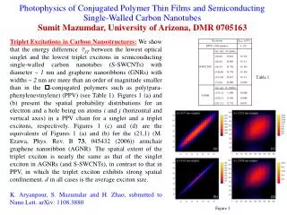
Supercritical Carbon Dioxide as Solvent for Polymer Thin Films. S. K. Satija,. Y.-S. Seo. NCNR. STONY BROOK. T . Koga, M. H. Rafailovich, J. C. Sokolov. K-JIST KOREA K.W. Shin. NG7 Reflectometer. Solid Substrate. scCO 2 exposure. Polymer Thin Films.

E N D
Supercritical Carbon Dioxide as Solvent for Polymer Thin Films S. K. Satija, Y.-S. Seo NCNR STONY BROOK T . Koga, M. H. Rafailovich, J. C. Sokolov K-JIST KOREA K.W. Shin
Solid Substrate scCO2 exposure Polymer Thin Films Confined geometry causes large differences in properties (glass transition, density, crystallinity, adhesion) as well as phenomena (phase separation/transition, chain dynamics) at surface or interface. air Question: Any differences in properties and phenomena between bulk and thin films in scCO2 ? 2Rg
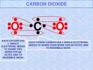
What is SCFs ? Substance P ( M P a ) T ( ° C ) c c C O 7 . 3 8 3 1 . 3 How do SCFs look like in microscopic scale? 2 2 2 . 0 3 H 0 3 7 4 . 1 2 1 3 2 . 5 1 1 . 3 9 N H 3 What is SCFs? P SCFs Liquid P c Solid <Schematic view of molecular distribution> Vapor T T c Key word “density fluctuations” Tc: critical temperature Pc: critical pressure
Neutrons i i Si High Pressure Neutron Reflectometry <Reflectivity geometry> qz Polymer (1) Thickness (2) Roughness (3) Density can be obtained
Pc 0 . 6 2 0 ° C 2 9 ° C n 3 2 ° C o i 3 6 ° C t a l 4 5 ° C 0 . 4 i D 5 0 ° C r a e n i L 0 . 2 2 0 5 0 ° C 1 5 Bulk film I 1 0 0 . 0 0 5 1 0 1 5 2 0 5 P r e s s u r e ( M P a ) 0 0 5 1 0 1 5 2 0 2 5 P ( M P a ) Both locus and shape for scattering intensity (density fluctuations) are similar to those of swelling !! Isothermal Swelling Behavior All swelling isotherms show the maxima near critical pressure (Pc) while bulk swelling has a plateau (~10%) with no maxima, i.e., very poor solvent. <Scattering intensity from pure CO2> deuterated styrene-butadiene copolymer (d-SBR, Mw=84k, 450 Å thickness)
Density Fluctuations 20 29 32 36 45 50 ºC P Supercritical Liquid 3 0 2 9 ° C 3 6 ° C > N CP 2 0 < “Ridge” / > 2 ) N D Gas ( < 1 0 5 0 ° C 2 0 ° C T 0 5 1 0 P r e s s u r e ( M P a ) 1 5 2 0 Density-Fluctuation-Induced Swelling A locus of maximal points is called as “ridge” Anomalous swelling of polymer thin films in CO2 is associated to the density fluctuation ridge. Density fluctuations can significantly enhance the solvent quality in thin films even when the bulk miscibility with CO2 is very poor.
w H2O/D2O Z Melittin 4 Deuterated Phospholipid 3 C18 Alkanethiol 2 1 (Ethylene Oxide)6 s Incident beam Reflected beam Melittin in Hybrid Bilayer Membranes Susan Krueger, Chuck Majkrzak, Joe Dura, Norm Berk, NCNR Curt Meuse, Anne Plant, NIST Biotechnology Div. Hybrid Bilayer Membrane Sample Scattering Length Density (SLD) Profile (z) Gold-coated Silicon Substrate
Deuterated Lipid Head Group CD2 Deuterated RNA Deuterated Protein Water RNA DNA Protein Lipid Head Group CH2 Contrast Variation Contrast ()
Hybrid Bilayer Membranes Data Used gold-coated substrates, chain-deuterated lipid and thin water reservoir to obtain data to high Q value. Qmax~ 0.7 Å-1 !
Hybrid Bilayer Membranes Data Fitting Used model-independent fitting technique to obtain SLD profile of biomimetic membranes. SLD Profiles (bilayer region only)
Models of Hybrid Bilayer Membranes with Mounir Tarek, NIST NCNR Used MD simulations and scattering length density profiles to obtain structural models of biomimetic membranes. Roughness
Conclusions • SLD profiles show : • there is no water in the (ethylene oxide)6 layer. • melittin perturbs the headgroup layer significantly, most likely causing the depletion of water in the layer. • although melittin lies in the headgroup region, it induces changes in the middle of the alkane region, most likely causing a change in tilt of the alkane chains. Krueger, S., Meuse, C.W., Majkrzak, C.F., Dura, J.A., Berk, N.F., Tarek, M., Plant A.L. (2001). Langmuir17, 511.
Amyloid β Peptide – Possible Mechanisms of Alzheimer’s Toxicity Frank Heinrich, Duncan McGillivray, Mathias Loesche, Carnegie Mellon Univ. Jim Hall, Univ. of California, Irvine Amyloid β forms ion channels which allow calcium uptake, leading to rapid neuronal degeneration or death. Amyloid β leads to a disruption (thinning) of the membrane without penetration.
The Biomimetic Membrane System INNER LEAFLET: Two alkyl tails joined through a glycerol to a thiolated hexa (ethylene oxide) “spacer” (WC14). This spacer supports the membrane above a gold-coated Si solid support, providing a ≈20Å, partly water-filled, sub-membrane space. OUTER LEAFLET: DOPC monolayer.
Neutron Reflectivity Data Used model-dependent fitting technique, simultaneously fitting data obtained using mixtures of H2O and D2O buffers. D2O buffer Other measurements made with mixtures of H2O and D2O buffers are not shown.
Scattering Length Density Profiles D2O buffer
Conclusions • SLD profiles show : • the inner leaflet is not affected by amyloid β. No Channel • a significant decrease of the membrane thickness in presence of amyloid β. Membrane Thinning