
Error Detection and Correction in Data Communication
E N D
Presentation Transcript
Error Detection and Correction Prof. Choong Seon HONG
9장 Error Detection and Correction 9.1 Types of Errors 9.2 Detection 9.3 Error Correction
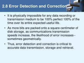
Error Detection and Correction • Data can be corrupted during transmission. For reliable communication, error must be detected and corrected • are implemented either at the data link layer or the transport layer of the OSI model
Type of Errors(cont’d) • Single-Bit Error ~ is when only one bit in the data unit has changed (ex : ASCII STX - ASCII LF)
Type of Errors(cont’d) • Multiple-Bit Error ~ is when two or more nonconsecutive bits in the data unit have changed(ex : ASCII B - ASCII LF)
Type of Errors(cont’d) • Burst Error ~ means that two or more consecutive bits in the data unit have changed
9.2 Detection • Error detection uses the concept of redundancy, which means adding extra bits for detecting errors at the destination
Detection(cont’d) • Redundancy
Detection(cont’d) • Detection methods • VRC(Vertical Redundancy Check) • LRC(Longitudinal Redundancy) • CRC(Cyclic redundancy Check) • Checksum
Detection(cont’d) • VRC(Vertical Redundancy Check) • A parity bit is added to every data unit so that the total number of 1s(including the parity bit) becomes even for even-parity check or odd for odd-parity check • VRC can detect all single-bit errors. It can detect multiple-bit or burst errors only the total number of errors is odd.
Detection(cont’d) • Even parity VRC concept
Detection(cont’d) • LRC(Longitudinal Redundancy Check) • Parity bits of all the positions are assembled into a new data unit, which is added to the end of the data block
Detection(cont’d) • CRC(Cyclic Redundancy Check) ~ is based on binary division.
Detection(cont’d) • CRC generator ~ uses modular-2 division. Binary Division in a CRC Generator
Detection(cont’d) Binary Division in a CRC Checker
Detection(cont’d) • Polynomials • CRC generator(divisor) is most often represented not as a string of 1s and 0s, but as an algebraic polynomial.
Detection(cont’d) • A polynomial representing a divisor
Detection(cont’d) • Standard polynomials
Detection(cont’d) • Checksum ~ used by the higher layer protocols ~ is based on the concept of redundancy(VRC, LRC, CRC ….)
Detection(cont’d) • Checksum Generator
Detection(cont’d) • To create the checksum the sender does the following: • The unit is divided into K sections, each of n bits. • Section 1 and 2 are added together using one’s complement. • Section 3 is added to the result of the previous step. • Section 4 is added to the result of the previous step. • The process repeats until section k is added to the result of the previous step. • The final result is complemented to make the checksum.
Detection(cont’d) • data unit and checksum
Detection(cont’d) • 예제 9.7 ( at a sender) Original data : 10101001 00111001 10101001 00111001 -------------- 11100010 Sum 00011101 Checksum 10101001 00111001 00011101 전송
Detection(cont’d) • 예제 9.8 ( at a receiver) Received data : 10101001 00111001 00011101 10101001 00111001 00011101 --------------- 11111111 Sum 00000000 Complement
9.3 Error Correction ~ can be handled in two ways when an error is discovered, the receiver can have the sender retransmit the entire data unit. a receiver can use an error-correcting code, which automatically corrects certain errors.
Error Correction(cont’d) • Single-Bit Error Correction • parity bit • The secret of error correction is to locate the invalid bit or bits • For ASCII code, it needs a three-bit redundancy code(000-111)
Error Correction(cont’d) • Redundancy Bits ~ to calculate the number of redundancy bits (R) required to correct a given number of data bit (M)
Error Correction(cont’d) • If the total number of bits in a transmittable unit is m+r, then r must be able to indicate at least m+r+1 different states 2r m + r + 1 ex) For value of m is 7(ASCII), the smallest r value that can satisfy this equation is 4 24 7 + 4 + 1
Number of Redundancy Bits (r) Total Bits (m+r) Number of Data Bits (m) 1 2 3 4 5 6 7 2 3 3 3 4 4 4 3 5 6 7 9 10 11 Error Correction(cont’d) • Relationship between data and redundancy bits
Error Correction(cont’d) • Hamming Code ~ developed by R.W.Hamming • positions of redundancy bits in Hamming code
Error Correction(cont’d) • each r bit is the VRC bit for one combination of data bits r1 = bits 1, 3, 5, 7, 9, 11 r2 = bits 2, 3, 6, 7, 10, 11 r4 = bits 4, 5, 6, 7 r8 = bits 8, 9, 10, 11
Error Correction(cont’d) • Redundancy bits calculation(cont’d)
Error Correction(cont’d) • Redundancy bits calculation
Error Correction(cont’d) • Calculating the r values Calculating Even Parity
Error Correction(cont’d) • Error Detection and Correction
Error Correction(cont’d) • Error detection using Hamming Code
Error Correction(cont’d) • Multiple-Bit Error Correction • redundancy bits calculated on overlapping sets of data units can also be used to correct multiple-bit errors. Ex) to correct double-bit errors, we must take into consideration that two bits can be a combination of any two bits in the entire sequence