Nuclear Science Symposium (NSS)
130 likes | 157 Vues
Explore the cutting-edge electronics system designed for the CMS Muon Drift Tube Chambers in this session from Nuclear Science Symposium. Learn about the components, features, performance, and integration of the Read-Out Minicrate in Madrid, Spain.

Nuclear Science Symposium (NSS)
E N D
Presentation Transcript
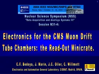
1 Nuclear Science Symposium (NSS) "Data Acquisition and Analisys Systems III" Session N31-4: Electronics for the CMS Muon Drift Tube Chambers: the Read-Out Minicrate. C.F. Bedoya, J. Marín, J.C. Oller, C. Willmott Electronics and Automation General Laboratory. CIEMAT. Madrid, SPAIN.
2 LHC & CMS. Compact Muon Solenoid LHC is a proton-proton collider Endcap´s CMS is a general purpose particle detector, designed to run at the highest luminosity of LHC and optimized for muon detection and track reconstruction. • Energies up to 7 TeV per beam • Bunch crossing period of 25 ns • Luminosity 1034 cm-2 s-1 N31-4: “Electronics for the CMS Muon Drift Tube Chambers: the Read-Out Minicrate.” C.F. Bedoya. CIEMAT. Madrid, SPAIN. Barrel 5 wheels • 15 m length, 21.5 m diameter, 12500 Tons • Large solenoid for generate up to 4 T. • Inside the solenoid: Tracker, ECAL, HCAL • Outside the solenoid: Muon system: - Cathode Strip Chambers (CSC), - Resistive Plate Chambers (RPC´s), - Drift Tube Chambers (DT´s). Large Hadron Collider Rome. October 15th to 22nd, 2004.
3 Qty: 250 DT Chamber SL 1 Honeycomb SL SL 2 N31-4: “Electronics for the CMS Muon Drift Tube Chambers: the Read-Out Minicrate.” C.F. Bedoya. CIEMAT. Madrid, SPAIN. 20 m copper link ROS MINICRATE Qty: 250 DAQ ROB Read-Out Board Qty: 1500 Rome. October 15th to 22nd, 2004. Muon DT Read-Out System CMS barrel transversal view DT chambers inside the iron yoke. 12 sectors, 4 stations/sector
4 N31-4: “Electronics for the CMS Muon Drift Tube Chambers: the Read-Out Minicrate.” C.F. Bedoya. CIEMAT. Madrid, SPAIN. Rome. October 15th to 22nd, 2004. Read-Out System Time digitalization related to Level 1 Accept trigger of the incoming signals from the Front-End electronics of the DT cells. Drift tube cell Tmax < 400 ns Drift velocity ~ 55 μm/ns Resolution < 200 μm => 1 ns hits L1A Trigger REQUIREMENTS: L1A Trigger • Overlapping triggers. • L1Accept maximum rate 100KHz. • L1A latency 3.2 s. • Charged particle rate 10KHz/channel Search window to accomodate max. drift time L1 Accept Latency ~3.2 s Bunch crossings T = 25 ns • Environmental radiation: neutron fluence 1010cm-2 charged particle flux 10 cm-2 s-1 10 years integrated dose 1Gy. • Up to 0.08T magnetic fields. • 10 years limited maintenance operation, etc.
5 N31-4: “Electronics for the CMS Muon Drift Tube Chambers: the Read-Out Minicrate.” C.F. Bedoya. CIEMAT. Madrid, SPAIN. Rome. October 15th to 22nd, 2004. ROB: Read-Out Board - Developed at CIEMAT. Based on the High Performance Time to Digital Converter (HPTDC) developed by CERN/MIC group. - 128 channels => 4 HPTDC/ROB, connected in a clock synchronous token-ring scheme with bypassing possibility. - Some features include: JTAG interface, power supply protection circuitry and V, I and T on board sensor. ROB PERFORMANCE: • Low resolution mode: 0.78125 ns /bin. Measured RMS resolution 260 ps. (Required resolution 1 ns) •Cross-talk < 350 ps. •Radiation tests at Cyclotron Research Centre (UCL). 5 1010 protons cm-2 at 60MeV MTBF(SEU, HPTDC and CPLD) ~ 3 days in the whole detector.
6 N31-4: “Electronics for the CMS Muon Drift Tube Chambers: the Read-Out Minicrate.” C.F. Bedoya. CIEMAT. Madrid, SPAIN. Rome. October 15th to 22nd, 2004. Minicrate Description It is an aluminum structure that contains: • Read-Out electronics (RO-MC): ROB´s + ROLINK • DT Muon Trigger system: Trigger boards (TRB´s) and Server Board (SB) • MC & Chamber control: CCB (Chamber Control Board) + CCB-link RO electronics is integrated sharing with the trigger system: •wire chamber signals: TRB´s connected on top of ROB´s receiving LVDS-TTL translated signals. • Timing & Trigger Control signals: 40.08MHz clock, L1Accept trigger, Event and Bunch counters reset, test pulse sequence commands. •power supplies: CAEN A3050 for 3.3V high current (42A, nominal voltage 4V) CAEN A3009 for digital 5V (1.8A, nominal voltage 6V) •cooling: water cooling system due to the magnetic field. •and mechanics: up to 40 different pieces designed to ease conductive refrigeration.
7 N31-4: “Electronics for the CMS Muon Drift Tube Chambers: the Read-Out Minicrate.” C.F. Bedoya. CIEMAT. Madrid, SPAIN. Rome. October 15th to 22nd, 2004. Read-Out Minicrate Integration of several ROB´s LVDS-TTL converted signals for TRB´s LVDS Data Signals from FE Chamber Transversal cross section: water cooling pipe 40 lines parallel bus: - power on lines - ROB´s addressing (4 bits) - JTAG interface lines - L1 Accept signal - Bunch & Ev. counter rst - Test Pulse control - 1-wire sensor interface ROB ROBUS - Individual channel disabling. - HPTDC bypassing possibility - Independent ROB operation. FAILURE IN ONE COMPONENT DOES NOT INTERFERE IN THE OTHERS. 3.3V power supply connector ROLINK cable. 200Mbps. Independent point to point 40.08 MHz clock cables. Length adjusted to compensated ROBUS skews. Clock cables: Separated ROB & TRB clocks Power filters
8 N31-4: “Electronics for the CMS Muon Drift Tube Chambers: the Read-Out Minicrate.” C.F. Bedoya. CIEMAT. Madrid, SPAIN. Rome. October 15th to 22nd, 2004. Read-Out Minicrate Operation Test pulse operation mode: testing and calibration of all the DT electronic chain. Artificial tracks are emulated at Front-End level, and then, selected channels are sequentially disabled to simulate vertical tracks along the chamber. RO-MC OPERATION MODE HAS BEEN THOROUGHLY TESTED AT LABORATORY: RO link reliability was tested with 30 m cable: BER <10-15 ROB power consumption ~ 3W, full MC ~130W. Water cooling at 20ºC water 1.5l/min provide maximum board temperature of 38ºC. ROB behaviour with temperature variations previously studied in cycling tests (0º-70º): small variations on regulator (5mV/30ºC), current (0.4mA/ºC) and time shifts ~ 14ps/ºC (max. 40ps/ºC at 40ºC). Lifetime tests of a ROB at 105ºC fully operational 4 months, no error found.
9 N31-4: “Electronics for the CMS Muon Drift Tube Chambers: the Read-Out Minicrate.” C.F. Bedoya. CIEMAT. Madrid, SPAIN. Rome. October 15th to 22nd, 2004. Read-Out Minicrate Operation ... AND ALSO AT DIFFERENT TEST BEAMS: With a 25 ns structured beam, similar to the one foreseen for LHC: Oct. And Nov. 01, Test beams at GIF, CERN: ROB and HPTDCvalidated. May 03, Test beam at GIF, CERN: MB3 MC connected to a chamber. Oct. 04, Test beam at H2, CERN: Two Chambers with MB1 and MB3 MC´s. ROB´S BURN-IN Before assembly on MC´s, ROB´s go through a burn-in process. The aim is screening for infant mortality, without stressing the boards. 1 week at 50ºC powered and clocked. 600 boards already “burned-in”, no failure found.
10 N31-4: “Electronics for the CMS Muon Drift Tube Chambers: the Read-Out Minicrate.” C.F. Bedoya. CIEMAT. Madrid, SPAIN. Rome. October 15th to 22nd, 2004. Read-Out Minicrate Production There are up to 20 types of read-out MC´s, depending on: - # channels of the DT chamber=> #ROB´s, from 3 to 7. - Position of the service side is different on each wheel => left and right MC´s. - Special chambers on CMS chimney location. Average weight ~ 8 Kg 2 meters 1 meter MC production is shared by CIEMAT, INFN Padova, INFN Bologna and RWTH Aachen. Each has manufactured a part of the 250 aluminium extrusions. CIEMAT has designed and produced most of the mechanical pieces and cables. MC assembly is performed in stages: 1. CIEMAT: where a Read-Out MC is assembled and tested. 2. Padova & Bologna: Trigger part assembly and full tests. 3. CERN: Assembly on DT chambers and final test. 12 to 16 MC/month foreseen rate. 39 Read-Out MC already assembled and tested.
11 N31-4: “Electronics for the CMS Muon Drift Tube Chambers: the Read-Out Minicrate.” C.F. Bedoya. CIEMAT. Madrid, SPAIN. Rome. October 15th to 22nd, 2004. RO-Minicrate Production Tests A test jig has been developed at CIEMAT to perform RO-MC functional testing in normal and test pulse mode, simulating input signals without using a DT chamber. - Check turn on of every board and short circuit flag line. - Insure proper ROB configuration: idcodes, PLL and DLL locking, buffers, etc. - Check Rob error signal status. - Monitorize 2.5V and 3.3V voltage, current and temperature of every ROB. - Check proper phase of 40MHz clock on every ROB and Trigger, Bunch and Event reset phase.
12 N31-4: “Electronics for the CMS Muon Drift Tube Chambers: the Read-Out Minicrate.” C.F. Bedoya. CIEMAT. Madrid, SPAIN. Rome. October 15th to 22nd, 2004. RO-Minicrate Production Tests - Data acquisition tests: 1º: one hit at a time to each channel. 2º: hits on every channel with HPTDC level disabling. 3º: simultaneous data on every channel. 4º: Test pulse sequences. Besides, always is checked: consecutive event number common event and bunch number on every ROB wordcount number HPTDC master identification ROB or HPTDC error and link unlock or parity error. Hit time digital measurement (value fixed by the test jig) These verifications insure: proper ROBUS operation (all lines), HPTDC´s configuration and control, CPLD operation, serializer, receivers, addressing circuitry, power supply circuitry, proper clock and rolink cables connection.... Functionality of every component and assembly of each element is verified. A purpose designed board has been developed at CIEMAT for the manufactured cable quality control.
13 N31-4: “Electronics for the CMS Muon Drift Tube Chambers: the Read-Out Minicrate.” C.F. Bedoya. CIEMAT. Madrid, SPAIN. Rome. October 15th to 22nd, 2004. Conclusions We conclude that the Read-Out Minicrate design and configuration works properly and accomplishes the imposed requirements. Therefore, we are confident in its proper operation inside the CMS environment. We have tried to minimize the limited maintenance problem with the employment of monitorization and sensoring elements, independent functional units and analysis of lifetime and burn-in tests. Read-Out MC production has already being launched, and the test jig designed and its functional tests have allowed to check for every error that a RO-MC could have due to assembly or to a component failure. We conclude that the design of the RO-MC is reliable for operation within the CMS detector.