Download
1 / 10
100 likes | 260 Vues
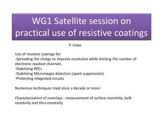
Experience with resistive coatings at Saclay. P. Colas. Use of resistive coatings for: Spreading the charge to improve resolution while limiting the number of electronic readout channels Stabilizing Micromegas detectors ( spark suppression) Protecting integrated circuits

E N D
Experiencewithresistivecoatingsat Saclay P. Colas • Use of resistivecoatings for: • Spreading the charge to improveresolutionwhilelimiting the number of electronicreadoutchannels • Stabilizing Micromegas detectors (spark suppression) • Protectingintegrated circuits • Numerous techniques triedsince a decade • Characterization of coverlays : measurement of surface resistivity, bulkresistivity and thru-resistivity and Carleton, Nikhef, Neuchatel
ILC-TPC : charge spreading Resistivebulk Micromegas Continuous RC circuit spreads the charge -> resolutionimprovement 60 µ resolutionat 0 drift with 3 mm pads ! Experience with resistive coatings
Also the resistive foil stabilizes Micromegas: no more breakdown, stable current Argon/Isobutane 90/10 Cr (SiO2)ncermet P.C., M. Dixit, I. Giomataris 2005 LC workshop, Stanford Experience with resistive coatings
Standard Micromegas Resistive Micromegas MAMMA beam test, 15 kHz hadron beam, October 2009 Experience with resistive coatings
ResistivedepositsalsoprotectTimePix Chips fromsparks (10 microns of aSi:H, 4-7 microns of SixNy (H. VdGraaf, N. Wyrsch) Experience with resistive coatings
Deposition of thinlayers (10 µ thick) of a-SiH (1013W.cm) Neuchatel, N. Wyrsch Possibility to add a doped layer on top Experience with resistive coatings
Weusedseveral techniques to measureresistivities. • May depend on voltage, pressure of the contact,… • Oftenseediscrepancies, inhomogeneities, unstabilities • Thru-resistivitysometimesinconsistentwith surface resistivity 4-point probe (Neuchatel) Circular probe Conducting tape, insulatingsubstrate lxLresistivesample = L/l ’squares’ Measureresistance, divide by number of squares Experience with resistive coatings
Diagnostic tools : thermal image of the prototype with a high-resistivity layer and a lower-resistivity layer on top (N. Wyrsch, EPFL, Neuchatel) Hot spots due to leakagecurrent Experience with resistive coatings