Data Flow Diagram
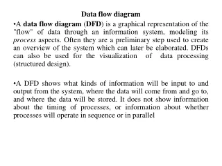
Data Flow Diagram. Data Flow Diagram:. "a network representation of a system. The system may be automated, manual, or mixed. The DFD portrays the system in terms of its component pieces, with all interfaces among the components indicated." - Tom DeMarco hence DFDs:

Data Flow Diagram
E N D
Presentation Transcript
Data Flow Diagram: "a network representation of a system. The system may be automated, manual, or mixed. The DFD portrays the system in terms of its component pieces, with all interfaces among the components indicated." - Tom DeMarco hence DFDs: focus on the movement of data between external entities and processes, and between processes and data stores
Analysis (What do we do?) Fact finding investigate business process and the current system Planning Analysis Design Implementation Maintenance Where do they fit in?
Design Describes how the system will fulfill the user requirements Planning Analysis Design Implementation Maintenance Where do they fit in?
overview • The Data flow diagram is a form of • This is a technique for organising and documenting the structure and flow of data through a system’s processes, and the procedures to be implemented by a system’s processes. • DFD help to represent and communicate • Information and data flows • Processes that handle or change data • Stored data • Sources and recipients of information and data
Why Conduct Process Modeling? • The reason we do process modeling is to improve the operation of a system, not just to change its physical form. • Start with understanding (Understand components of current logical or physical system for purpose of rebuilding in a different physical form/technology, possibly with some changed functionality) • Then analyze for improvements or where to add new functionality (Find inefficiencies in current system) • Then specify re-engineered system
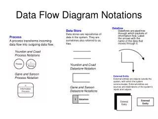
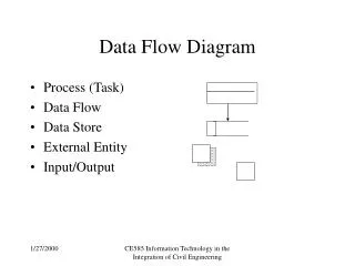
Components • A DFD is made up of four components: processes, external entities, data flows and data stores. • Processes • External entities • Data flows • Data stores
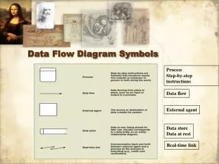
External Entity components • Entities • These are the places which provide the organisation with data, or have data sent to them by the organisation (e.g. customers, partners, government bodies). • Form the boundaries of the system. • The system and external entities exchange data in the form of data flows. • Must be named, titles preferred to names of individuals - use a noun
Process box components 2. Process • Jobs that are done with the data.
Data Flow Logs in components 3. Data Flows • Connects the processes, external entities and data stores • Arrows show how data flows from one place to another • Label the arrows with the name of the data that moves through it e.g. Customers logs into systems
Data Store Data Store Data Store D1 M1 T1 Components 4. Data Stores • Represents holding areas for collection of data, processes add or retrieve data from these stores • Only processes are connected to data stores • They can be manual, digital or temporary. Manual Data Store = M1 Digital Data Store = D1 Temporary Data Store = T1
Process box Data Flow External Entity Data Store D1 Notation • Data Flow • Process • External Entity • Data Store
Benefits of DFD • Provide a pictorial, non-technical representations • Quick to produce and easy to amend • Concise system descriptions
Logical versus physical models • What versus How • Shows what a system is or does • Focuses on how the business operates • Is implementation-independent • Shows how a system operates • Is implementation-dependent because it shows how a system is physically and technically implemented • Systems analysts use logical models to depict business requirements, and physical models to depict technical designs • System analysis activities tend to focus on the logical models
Context level dfd • The Context Level DFDattempt to show the workings of the entire system at a glance. • It is the and the first to be drawn • This level consists of • The process description usually outlines in general terms what the system is or does, for example, ‘Order Processing System’, ‘Video Rental Systems’. • The single process represents the entire system • Depicts the interaction between the system and external entities. • This level
Context level data flow diagram Process b. Entity a. Entity
Data Store D1 Rules for drawing DFDs... 1. • External entities cannot flow directly to each other • A data flow cannot link a data store to an external entity • Data cannot move between data stores without first being processed a. Entity a. Entity x x Communicates Communicates b. Entity
Rules for drawing DFDs... 1. All data flows must flow to or from a process continued..
Rules for drawing DFDs... 2. A process must have at least one input flow and one output flow • A arises when a process has input flows but no output flows • A is a situation which occurs when a process has outputs but no input flows. Process Process
Rules for drawing DFDs... 3. The inputs to a process must be sufficient to produce output flows. • If a process has outputs that are greater than the sum of its inputs, a is said to occur 4. The inputs to a process must be sufficient to produce output flows. • When naming data flows, adjectives should be used which show how processing has changed the data flow.
DFD – Common Errors Black Hole Gray Hole Miracle
Rules for drawing DFDs... • Data flows cannot cross each other • To overcome this problem, data stores and entities can be . • However, processes must never be duplicated • Data flows must be unidirectional Additional rules • Entities must be • Title = “Context Level DFD” and System or Company Name
Rules for connecting processes, data stores, and entities in a DFD
Steps in Constructing Context Level DFD • You will be supplied with a piece of narrative text describing a particular system. Read and re-read this text. • Extract and state a set of assumptions from the narrative text. • Identify the entities from the text – these will be depicted by nouns. • Highlight the process for the context level DFD • Identify data flows from the text – data flows are usually nouns or noun phrases. • Construct the Context Level DFDusing all the preceding information. Name and label the entities, data flows and name the main process.
Creating a Set of DFDs • Draw a Context Diagram • Put a title on the page = Context Level DFD for ‘name of company’. • Draw the context diagram so it fits on one page • Use unique names within each set of symbols • Provide a unique name and reference number for process
Lab work: Payroll System Context Level DFD • XYZ LTd. is a nationwide retail chain. Management is considering conducting Systems Analysis and Design with a view to computerising the payroll system. • Hours worked per employee per month are forwarded by the Personnel Department. This is used to create an employee time record for each employee and this is held in the Employee Time File. This is used to calculate Gross Pay, and Gross Pay is used to determine net pay. Pay slips are issued on the last Friday of every month. • The employee Master File must be updated on a regular basis. One instance which necessitates updating the system is when a new employee joins the firm. The Personnel Department gives the payroll system all new staff details. When an Employee gets married or moves house, details of the name/address change are given to the payroll system. Pay cheques are then prepared. • Management is in charge of salary changes – these are input to the Employee Master File when the time arises. Every month, management is sent a cash list with details of salary payments for each employee for the month previous. Required: • Draw up a reasonable set of assumptions, based on the narrative above. • You are now required to construct a Context Level DFD based on those assumptions, to help the company in its efforts computerise the payroll system.
Assumptions • Assumptions 1(a): • It is assumed that when employee details change, such as when he/she gets married or moves house, it is the responsibility of the individual employee to notify the payroll system as to name/address changes.
Context level • Identify Process • Payroll System • Identify entities a. Personnel Dept b. Management c. Employee • Identify data flows • Hours Worked • Salary Changes • Cash List • Pay Cheque • Name/Address Change • New Staff Details
Lab work: Payroll System Context Level DFD • XYZ LTd. is a nationwide retail chain. Management is considering conducting Systems Analysis and Design with a view to computerising the payroll system. • Hours worked per employee per month are forwarded by the Personnel Department. This is used to create an employee time record for each employee and this is held in the Employee Time File. This is used to calculate Gross Pay, and Gross Pay is used to determine net pay. Pay slips are issued on the last Friday of every month. • The employee Master File must be updated on a regular basis. One instance which necessitates updating the system is when a new employee joins the firm. The Personnel Department gives the payroll system all new staff details. When an Employee gets married or moves house, details of the name/address change are given to the payroll system. Pay cheques are then prepared. • Management is in charge of salary changes – these are input to the Employee Master File when the time arises. Every month, management is sent a cash list with details of salary payments for each employee for the month previous. Required: • Draw up a reasonable set of assumptions, based on the narrative above. • You are now required to construct a Context Level DFD based on those assumptions, to help the company in its efforts computerise the payroll system.
Assumptions • Assumptions 1(b): • It is assumed that when employee details change, such as when he/she gets married or moves house, the personnel department is responsible for informing the payroll system. The personnel department updates the payroll system directly. • The Employee is notified when changes are made by the Personnel Dept. • The Personnel Dept receives an acknowledgement that states Employee file is updated.
Validating the DFD • Syntax errors – diagram follows the rules • Assure correct DFD structure • For each DFD:Check each process for: • A unique name: action verb phrase; number; description • At least one input data flow • At least one output data flow • Output data flow names usually different than input data flow names • Between 3 and 7 processes per level 1+ DFD
Validating the DFD • For each DFD: • Check each data flow for:A unique name: noun; description Connects to at least one process Shown in only one direction (no two-headed arrows) • Check each external entity for: A unique name: noun; description At least one input or output data flow • Check each data store for: A unique name: noun; description At least one input data flow At least one output data flow
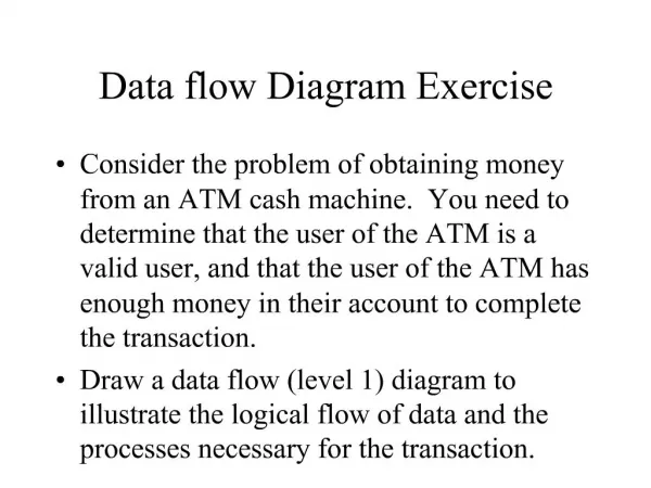
exercise Precision Tools sells a line of high-quality woodworking tools. When customers place orders on the company’s Web site, the system checks to see if the items are in stock, issues a status message to the customer, and generates a shipping order to the warehouse, which fills the order. When the order is shipped, the customer is billed. The system also produces various reports, such as inventory reports for Accounting. • Draw a context diagram for the order system • Document any assumptions you may have made about the system.