Download
1 / 1
20 likes | 189 Vues
P-14462 Tethered Glider. TEAM MEMBERS. INTRODUCTION.

E N D
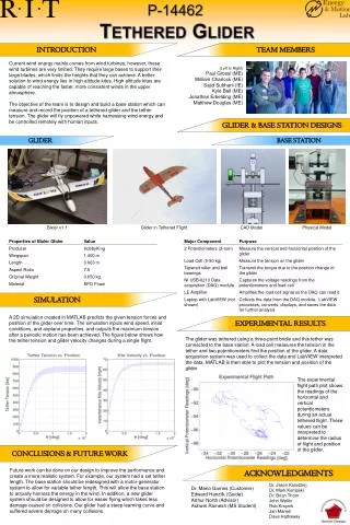
P-14462 Tethered Glider TEAM MEMBERS INTRODUCTION Current wind energy mainly comes from wind turbines; however, these wind turbines are very limited. They require large bases to support their large blades, which limits the heights that they can achieve. A better solution to wind energy lies in high altitude kites. High altitude kites are capable of reaching the faster, more consistent winds in the upper atmosphere. The objective of the team is to design and build a base station which can measure and record the position of a tethered glider and the tether tension. The glider will fly unpowered while harnessing wind energy and be controlled remotely with human inputs. (Left to Right) Paul Grossi (ME) William Charlock (ME) Sajid Subhani(IE) Kyle Ball (ME) Jonathan Erbelding (ME) Matthew Douglas (ME) GLIDER & BASE STATION DESIGNS GLIDER BASE STATION Glider in Tethered Flight Physical Model Bixler v1.1 CAD Model SIMULATION A 2D simulation created in MATLAB predicts the given tension forces and position of the glider over time. The simulation inputs wind speed, initial conditions, and airplane properties, and outputs the maximum tension after a periodic motion has been achieved. The figure below shows how the tether tension and glider velocity changes during a single flight. EXPERIMENTAL RESULTS The glider was tethered using a three-point bridle and this tether was connected to the base station. A load cell measures the tension in the tether and two potentiometers find the position of the glider. A data acquisition system was used to collect the data and LabVIEW interpreted the data. MATLAB is then able to plot the tension and position of the glider The experimental flight path plot shows the readings of the horizontal and vertical potentiometers during an actual tethered flight. These values can be interpreted to determine the radius of flight and position of the glider. CONCLUSIONS & FUTURE WORK ACKNOWLEDGMENTS Future work can be done on our design to improve the performance and create a more realistic system. For example, our system had a set tether length. The base station should be redesigned with a motor-generator system to allow for variable tether length. This will allow the base station to actually harness the energy in the wind. In addition, a new glider system should be designed to allow for easier flying which takes less damage caused on collisions. Our glider had a steep learning curve and suffered severe damage on many collisions. Dr. Jason Kolodziej Dr. Mark KempskiDr. Brian Thorn John Wellin Rob Kraynik Jan Maneti Dave Hathaway Dr. Mario Gomes (Customer) Edward Hanzlik (Guide) Arthur North (Advisor) Ashwin Ramesh (MS Student)