Download
1 / 25
250 likes | 457 Vues
Team 5 Aerodynamics PDR #2. Scott Bird Mike Downes Kelby Haase Grant Hile Cyrus Sigari Sarah Umberger Jen Watson. Preview. Airfoil Sections and Geometry Aerodynamic mathematical model Launch Conditions Endurance. Walk-Around. Data Boom. Conformal Pod. Engine. Landing Gear.

E N D
Team 5 Aerodynamics PDR #2 • Scott Bird • Mike Downes • Kelby Haase • Grant Hile • Cyrus Sigari • Sarah Umberger • Jen Watson Aero PDR #2
Preview • Airfoil Sections and Geometry • Aerodynamic mathematical model • Launch Conditions • Endurance Aero PDR #2
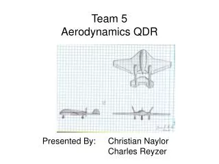
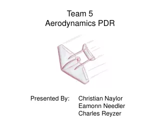
Walk-Around Data Boom Conformal Pod Engine Landing Gear Aero PDR #2
Aircraft 3-view Aero PDR #2
Wing Geometry • Wing • Airfoil NACA 2412 • Aspect Ratio 7 • Span 14 (ft) • Chord 2 (ft) • Planform Area 28 (ft^2) • Taper Ratio 0 (deg) • Dihedral 0 (deg) • Sweep Angle 0 (deg) Aero PDR #2
Horizontal Tail Geometry • Horizontal Tail • Airfoil NACA 0012 • Aspect Ratio 5 • Span 7 (ft) • Chord (average) 1.38 (ft) • Planform Area 9.64 (ft^2) • Taper Ratio 0.8 • Sweep Angle 5 (deg) Aero PDR #2
Vertical Tail Geometry • Vertical Tail • Airfoil NACA 0012 • Aspect Ratio 2 • Span 2.8 (ft) • Chord (average) 1.38 (ft) • Planform Area 3.9 (ft^2) • Taper Ratio 0.73 • Sweep Angle 10 (deg) Aero PDR #2
Lift Methodology • Used XFOIL to get NACA 2412 2-D data • Converted 2-D data to 3-D data for wing CLo and CLα • Used XFOIL to get NACA 0012 horizontal tail data • Used method described in Roskam Part VI, CH8 for CLδe Aero PDR #2
Aerodynamic Mathematical Model of Lift • CL= CLo + CLα* α + CLδe *δe • CLα = Cl α/ (1 + (Cl α/ (π* e * A))) [rad-1] • CL = Cl * (CLα/Cl α) • CLδe = CLα_ht* ηht * Sht / Sref * τe [rad-1] • ηht = f (Sht_slip, Sht, Pavailable, U, Dp, qbar) • (Roskam Part VI, CH8) Aero PDR #2
Summation of individual components for CDo Wing, fuselage, horizontal tail, vertical tail CD=CDo + k * CL * CL CDo = Σ CDo(i) CDo(i) = (Cf * FF * Q * Swet) / Sref k = 1 / (pi * AR * e) Aerodynamic Mathematical Model of Drag Aero PDR #2
Moment Methodology • Used method described in Roskam, Chapter 3 of AAE 421 Book to find individual components of moment equation Aero PDR #2
Aerodynamic Mathematical Model of Moments • CM = CMo + CMα* α + CMδe *δe • (α and δe in degrees) • CM0 = Cmac_wf + CL0_wf*(xbar_cg - xbar_acwf) + CLalpha_h*eta_h*(S_h/S)*(xbar_ach - xbar_cg)*epsilon • CMalpha = (x/cw)*CLalpha_wf*(xbar_cg - xbar_acwf) - CLalpha_h*eta_h*(S_h/S)*(xbar_ach - xbar_cg)*(1 – depsilon/dalpha) • CMdele = -CLalpha_h*eta_h*Vbar_h*tau_e Aero PDR #2
Aerodynamic Mathematical Model Summary • CL= 0.1764 + 7.941 (rad-1)* α + 1.925 (rad-1)* δe • α and δe are in radians • CD = .036 + .0522 * (.1764 + 7.941 (rad-1) * α)2 • Cm= - 0.0280 - 0.1562* α- 0.0898*δe Aero PDR #2
Launch Conditions Known Values • W = 49.6 lbs • S = 28 ft2 • ρ = 0.0023328 slug/ft3(at 600 ft) • CLmax:To = 0.8*CLmax = 1.44 VTO = 39 ft/s Aero PDR #2
Launch Conditions from EOM Normal Drag Thrust Our Airplane Friction Weight Aero PDR #2
Launch Conditions from EOM integration • STO = 76 ft • Constriant of 127 ft • tTO = 3.7 s Aero PDR #2
Endurance Known Values • Bhp = 3.7 hp • ηp = 0.40 • Cbhp = 0.0022 lb/s-hp • Wi = 49.6 lbf • Wf = 43.6 lbf • Using 1 gallon @ 6 lbf • L/D = 10.39 • 12*.866 (86.6% of L/Dmax when flying @ Vmin power) Aero PDR #2
Endurance • V = [2*W/( ρ*S)*(K/(3*CDo))1/2] ½ • (Raymer, eq 17.33) • K = 1 / ( pi * AR * e ) • Vmin@min power = 32.5 ft/s • E = (L/D)*[(550*ηp)/(Cbhp*V)]*ln(Wi/Wf) • (Raymer eq 17.31) E = 75.5 minutes Aero PDR #2
Future Work • Resize flaps for landing • Verify known values • Cbhp • Weight reduction from extra fuel (Endurance) Aero PDR #2
Review of Today’s Presentation • Wing Geometry and Size • 3-view of aircraft • Aerodynamic mathematical model • Launch Conditions • Endurance Aero PDR #2
Questions Questions?? Aero PDR #2
References Roskam AAE 421 Book Raymer Aircraft Design: A Conceptual Approach AAE 251 Book Introduction to Aeronautics: A Design Perspective Aero PDR #2
Putting EOMs into MATLAB • Put state space EOMs into MATLAB • Used ode45 command to integrate EOMs • Inputs to the code are initial conditions for position and velocity • Used x(0) = 0.1ft and v(0) = 1ft/s to eliminate singularities • Code output position and velocity as a function of time Aero PDR #2
EOM file in MATLAB Aero PDR #2