GWADW, May 2012
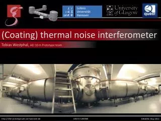
(Coating) t hermal noise interferometer. Tobias Westphal , AEI 10 m Prototype team. http://10m-prototype.aei.uni-hannover.de. LIGO G-1200560. GWADW, May 2012. Coating thermal noise basics. Advanced LIGO. AEI 10m Reference cavity. AEI 10m SQL Interferometer. Origin:

GWADW, May 2012
E N D
Presentation Transcript
(Coating) thermal noise interferometer Tobias Westphal, AEI 10 m Prototype team http://10m-prototype.aei.uni-hannover.de LIGO G-1200560 GWADW, May 2012
Coating thermal noisebasics Advanced LIGO AEI 10m Reference cavity AEI 10m SQL Interferometer Origin: High reflective coatings are based on amorphous thin films Mechanical losses couple mirror and heat bath → Thermal fluctuations «» Displacement noise (Fluctuation Dissipation Theorem) Workarounds: Lower temperature (change everything) Change materials Change structure Remaining problem: Test theory Measure offresonant thermal noise (done @ high f > 500Hz)
Historyof CTN Longlasting discussion about theory Frequency independent loss: structural damping Velocity proportional damping: viscous damping Experimental work: Structural damping in rotating rods: 1927 Viscous damping of a torsion balance: 1995 Fluctuation dissipation theorem validated for low loss material (fishing line): 1995 → Assuming FDT validity, only frequency dependence of loss needs to be measured Off resonant thermal noise (coating) measured 2003 Again 2004: 5x lower loss angle than expected
Plannedobservationof CTN Problem: Required sensitivity comparable to big interferometers → Similar effort! Use infrastructure of AEI 10m Prototype Vacuum space available Stabilized laser Seismic pre-isolation → Shrink frequency reference cavity & make it sensitive to CTN
AEI 10m Prototype layout Pre mode cleaner Tap off 10% Khalili cavity 10 m Fabry-Perot arm cavity Finesse ca. 670 ~ 8 W input @ 1064 nm BS ITM Frequency-referencecavity: Length: 10.6 m Finesse: 7300 IETM EETM
TNI design Beyondthermal noise • Test suspendedinterferometryclosetoopticalinstability • The future (exchange a singlemirror) • AlGAscoatings • Gratings • Bondingloss Fabry Perot Interferometer • Suspended 860g mirrors • Substrate: Fusedsilica • Coating: Tantala/Silica • 10 cm length (on onetable) • Plane/concave design • Small spotsize (tunable) Alignment & Control • Pound Drever Hall locking • Differential wavefrontsensing • Spot positioncontrols? • Localcontrol
TNI sensitivity TNI in a nutshell Input power: 1mW Circ. power: 2W Finesse: ≈ 6000 Big spot: 1mm Small spot: 70µm Limitations: Seismic (low f) CoatingBrownian (≈20Hz-5kHz) Shotnoise (high f) Pay attentionto thermoelasticnoise → shallowerslopeatlowfrequencies!
Frequencyreferencecavity Feedback: • Laser temperature (< 1Hz) • Laser PZT (< 10 kHz) • Phase correcting EOM (< 250 kHz) Inter tabledistance → lengthreference Roundtriplength 21.2 m Finesse 7300 Input power 130 mW Mirrormass 860 g (→ GEO MC)
Seismicpreisolation Passive lowfrequencyisolationtables • Reducermsseismicnoise • Isolation aroundmirrorsuspensionresonances → weakeractuators • Ease lock aqquisition
Mirrorsuspensions Seismic noise isolation above resonance Ultimate limit: Thermal noise @ last stage Almost Reference cavity design: Three horizontal, two vertical stages Cantilevers inside the upper mass two wires attached to each → better pitch damping 850 g per stage (mirror 10 cm x 5 cm) Steel wires, last stage 55 µm Ø (≈30% loaded) Local control at uppermost stage (passive filtering of actuation noise) Fast alignment by steering mirrors Reaction pendulum for fast longitudinal actuation
Localcontrol design Basis Transform: Uppermass DOFs → Actuators Basis Transform: Sensors → Uppermass DOFs Spot position Alignmentcontrol lowpass Localdamping BOSEM 1 whitening dewhitening watchdog BOSEM 1 long Filter pitch Filter side Filter roll Filter vert Filter yaw Filter Position sensing • 6 Shadowsensors per uppermass (BOSEMs) • 3E-10m/√Hz @ 1Hz • 0.7mm dynamicrange • Onesuspensionequippedwith OSEMs for higherdynamicrange? Signal processing • Digital basistransform & filtering (CDS) • Two separate paths (alignment, damping) • Hardware watchdog (rmscurrentreadout)
Localcontrolperformance Projectionofsuspensionnoise @ lowermass → resultsfulfill (referencecavity) requirements
Spotsizetunability • Setup & Performance • Modematchingoptimized for w0=58µm • Scanning 1mm reaches to instability • Modemismatched light is reflected • Junk light contributes only shotnoise Cavity basics Radius of curve mirror is fixed to 100mm Optical stability requires L < radius of curvature (ROC) Close to instability (L≈ROC) spotsize (w0) drops quickly
Spotsizechanging Assuming perfect modematching → Lenses need to be moved → Every setup is different
Spotsizechanging Assuming fixed modematching → optimized for ≈58µm → non modematched light contributes shotnoise (is directly reflected)
Spotsizesensing Solution: • Bulls eye photo detector behind TNI • Calibration via CCD beam analyzer Problem: Thermal noise depends on spotsizes on mirrors Spotsize strongly changes with cavity length (close to instability) → Online monitoring of waist
Crazymirrors Increase losses (thermal noise ~ √N) AR HR Extra thick HR coating No transmitted beam AR coating underneath HR Raise Brownian and thermo elastic noise Same reflectivity AR coating on top of HR Raise thermo refractive noise Same reflectivity
The team http://10m-prototype.aei.uni-hannover.de • Ken Strain: Scientific leader • Stefan Goßler: Coordinator • Gerhard Heinzel: LISA/LPF related experiments • Yanbei Chen, KentaroSomiya, Stefan Danilishin: Experiment design, noise analysis • Roman Schnabel: Squeezing and QND experiments • HaraldLück: Vacuum system and GEO 600 related experiments • Hartmut Grote: Electronics and GEO 600 related experiments • GEO operators: Filter design and construction, environmental monitoring • Andreas Weidner: Electronics design • KasemMossavi: Vacuum system and pumps control • BennoWillke, Jan HendrikPöld, Patrick Oppermann, ThimoteusAlig: High power laser • GerritKühn, Michael Born, Martin Hewitson: Real time control system • Alessandro Bertolini, Alexander Wanner, Gerald Bergmann: Isolation tables • Katrin Dahl: Suspension Platform Intererometer • SinaKöhlenbeck: Digital interferometry • Fumiko Kawazoe, Manuela Hanke: Frequency reference cavity • Stefan Hild, Sabina Huttner, Christian Gräf:Interferometric sensing & control • Giles Hammond, Tobias Westphal: (Monolithic) suspensions