Download
1 / 54
570 likes | 710 Vues
Spin currents in non- collinear magnetic tunnel junctions and metallic multilayers. Peter M Levy New York University, USA. Background to TMR. Long before GMR per se was discovered, there existed, by 1972, another

E N D
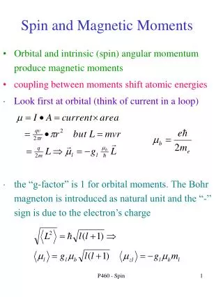
Spin currents in non- collinear magnetic tunnel junctions • and • metallic multilayers Peter M Levy New York University, USA
Background to TMR Long before GMR per se was discovered, there existed, by 1972, another magnetoresistive effect that resembles Current Perpendicular to the Plane Magnetoresitance (CPP-MR); that is tunneling magnetoresistance (TMR). The difference between them is the spacer layer between the magnetic layers. In GMR it’s a nonmagnetic metal whereas for TMR it’s an insulator. The difference is important because it determines the type of conduction process that transmits the current between the magnetic entities [grains or layers]. For a metallic spacer, transmission takes place by conduction electrons at the Fermi level; whereas for an insulating spacer there are no electrons at the Fermi level as the insulator falls in a gap between conduction and valence bands: therefore electrons “tunnel”, in the quantum mechanical sense, between the magnetic entities. Long before GMR per se was discovered, there existed, by 1972, another magnetoresistive effect that resembles Current Perpendicular to the Plane Magnetoresistance (CPP-MR); that is tunneling magnetoresistance (TMR). The difference between them is the spacer layer between the magnetic layers. In GMR it’s a nonmagnetic metal whereas for TMR it’s an insulator. The difference is important because it determines the type of conduction process that transmits the current between the magnetic entities [grains or layers]. For a metallic spacer, transmission takes place by conduction electrons at the Fermi level; whereas for an insulating spacer there are no electrons at the Fermi level as the insulator falls in a gap between conduction and valence bands: therefore electrons “tunnel”, in the quantum mechanical sense, between the magnetic entities.
Conduction electrons have wavefunctions that oscillate between positive and negative amplitudes with a frequency related to the wavelength at the Fermi level, e.g., for a typical 3d transition-metal this is on the order of 1 Å. This is a rapid oscillation so that minute details of the roughness of the interfaces [of this lengthscale] between the spacer and magnetic layers affect the electrical conduction process. Indeed this is why the details of the roughness and diffusion at the interfaces are crucial for predictions of ab-initio calculations of GMR in metallic multilayers. Electrons that tunnel between magnetic entities do not have oscillatory wavefunctions; rather they decay exponentially. In this case details about the interfaces with the magnetic entities are less important. This is the primary reason ab-initio calculation had a far greater success in predicting TMR behavior ..
TMR was first observed in the tunneling between grains in granular nickel films by Gittleman et al in 1972. Michel Jullière was the first to observe it in the more conventional multilayer geometry in 1975 known as Magnetic Tunnel Junctions (MTJ) where he found 14% TMR at low temperatures for Fe(iron)/Ge(germanium) /Co(cobalt); this was followed by Maekawa and Gäfvert’s observations, in1982, of TMR by using nickel, iron and cobalt electrodes across nickel oxide barriers. Then, in 1995, Miyazake and Moodera both observed reproducible TMR in MTJ’s. Their work came at a propitious time when there was increased interest in magnetoresistive elements and it gave rise to a flurry of activity in this field. The first phenomenological models of TMR were provided by Gittleman et al. and Jullière, and theoretical work on MTJ’s was first done by John Slonczewski. Ab-initio calculations came close on the heels of the findings of Miyazake and Moodera and were based on the Landauer-Büttiker formalism of conduction.
This formalism, which is suitable for ballistic transport, was previously used for the contribution of band structure to the GMR in metallic multilayers. Transport in metallic systems is usually described as diffusive; this is in large part due to the oscillatory wave functions at the Fermi surface which are the carriers in metallic structures (of course, impurity scattering is also necessary). However, while the transport in the ferromagnetic electrodes may be diffusive, the tunneling across the insulating barrier is through evanescent states and this part of the conduction can be ballistic, in which case one can apply a Landauer-Büttiker-like analysis to TMR. Also, as tunneling currents are small compared to currents in metals, the role of current-driven charge and spin accumulation do not have a big effect on the resistivity of MTJs, i.e., their neglect does not change one’s predictions for the TMR of MTJs.
Density matrix: Rotated: Transmission amplitude:
Charge current Spin current
Inelastic scattering; let’s confine ourselves to T=0K: Only possible to generate magnons when they are emitted by spin current.
Evaluation of sum over magnons Interfacial magnons where superscript i stands for transmission amplitudes for interface magnon production tmi . Remember the spin current due to elastic scattering is:
For tm=0 Equilibrium spin current None other than interlayer exchange coupling Out of equilibrium spin current
Resolution: 2nd order perturbation of the free electron energy due to local moments, i.e., RKKY 2nd order correction to the energy Produces precession of conduction electrons spin
When we focus on spin dependent transmission By using this spin dependent amplitude and taking the components of the ensuing spin current transverse to the magnetization of the upstream electrode, the elastic contribution to the torque is:
The only current or bias induced excitations are from and we have to evaluate so that the inelastic spin-flip contributions to the torque are:
While for the elastic terms (non spin-flip magnetic as well as for direct transmission) we found: The new feature for the inelastic contributions to the torque are that they are not in the same direction for the two electrodes:
Definition of spin torque: Elastic Inelastic Magnons created by hot spin current assist elastic torque on upstream electrode, but for downstream are in opposite sense.
How does one understand this? Elastic torque comes from spin current in tunnel junction being the vector sum of the polarized currents from the source and drain, i.e., from upstream and downstream electrodes. From our calculations we find When angular momentum is transferred between a spin current whose polarization is noncollinear to the magnetization of an electrode, torque is produced. The component of the vector sum of difference between spin angular momentum gained by current and that lost by background magnetization that is transverse to electrode’s magnetization is the torque created by this exchange of magnons between noncollinear entities.
At T=0K hot spin currents can only lower the polarization of electrodes. Note the sign in definition of torque due to transfer of angular momentum
From experiments on MTJ’s one find that the ratio of the spin torque to the current is relatively flat as one increases the bias. The (charge) current as a function of bias is:
We have evaluated the spin torques and charge currents by using the parameters we previously found were able to fit the zero-bias anomaly found for Co/Al2O3/CoFe: The ratio of the spin torque to the current for the upstream electrode is
and the ratio of the spin torque to the current for the downstream electrode is This agrees with data as free layer is upstream for forward bias . Reversing polarity we replace in above expression; noting that the free layer is now downstream we find the torque to current ratio remains relatively flat; in agreement with the data.
Conclusion: • Magnon production in magnetic electrodes is able to explain • how the spin torque increases with bias even though the • TMR decreases. • Our results are for the range + 200 meV; for higher bias one • should take into account the change in barrier profile with • bias. • In and of itself the change in barrier profile with bias cannot • explain the data. • See PRB 71,024411(2005). • But see PRL 97, 237205(2006).
Differences between tunnel barrier and metallic spacer Primary is lack of equilibrium coupling; its all current driven For example
In a magnetic tunnel junction the spin current is Js= βJe cos [θ/2]
The spin current in the middle of a nonmagnetic spacer between two magnetic layers is parallel to the sum of the magnetizations, and its magnitude is For cobalt is of the order of 0.02 for cobalt.
The spin current at the interface reaches its maximum of when the angle between the local magnetizations θ* is Note: θ* is close to π when λ ≪ 1.
The magnitude of the spin-current in a metallic junction is enhanced by a factor of λ-1 compared to the bare spin current βJe cos (θ/2). This comes from the interplay between longitudinal and transverse accumulations; even though the transverse components of the spin current are absorbed within a region of λJ of the interface.
Out of equilibrium effects control spin transfer in metallic structures Several approaches: • Maintain phase coherence (ballistic) Landauer-Keldysh; see Edwards et al. PRB71, 054407 (2005) • Discard coherence (diffusive) Layer-by-layer, e.g., Valet-Fert Whole potential
To write an out of equilibrium spin current The devil is in the details The energy minimum principle does not hold for systems out of equilibrium, even under steady state conditions For example, one can induce a coherence (to carry transverse spin currents) between states that in equilibrium are not.
The field operators in the propagators are found from the equation of motion they obey, i.e., the Schrödinger equation. The propagators themselves are found from their equation of motion. At the end of the day we arrive at the distribution function by taking the Wigner transform of the propagators,
Boltzmann equation of motion determines the distribution function 1-Attention must be paid to the different k states in the distribution function. Conventionally for spin split bands there are more than one, but most people use an equation of motion appropriate for only one k state Band structure of Co
2- In addition there’s the transmission of information about out-of-equilibrium distributions from one layer to another. One has to match functions across layers by using the transmission and reflection coefficients. Injection Propagation
In equilibrium m and s are spin indices This leads to the “mixing conductance” in the conventional view,i.e., the transfer of spin current from one spin channel to the other across the interface. A good example of a DOAmodefor propagating transverse waves. However, for transverse distribution function for currents A is the new current induced spin-flip term
Transmission of out-of-equilibrium distributions across interface fout fout Conventional Tequil Noncollinear multilayers one should also consider fequil fout Tout The following does not enter in linear response: fout fout Tout
To obtain off-diagonal amplitudes requires one to consider the role of out-of-equilibrium spin accumulation created at one interface on a second interface when the magnetic layers are noncollinear, i.e., current-driven symmetry breaking. This leads to out-of-equilibrium corrections to the scattering amplitudes, or transmission and reflection coefficients. For spin currents its all about transparency of interfaces to propagating transverse waves.
For collinear structures the out-of-equilibrium corrections are merely changes in population of existing states; they are insignificant. However, for noncollinear multilayers symmetry is broken and this requires one to define new basis states. These out-of-equilibrium corrections can be sizeable.
Spin torque as a function of angle between layers for three different cases of current induced spin flip
Is it necessary to introduce out-of-equilibrium corrections when using approaches other than the layer-by-layer? The point is rather that is necessary to do calculations that are fully self-consistent. In the layer-by-layer approach as it has been applied to noncollinear multilayers only the transport within layers is determined self-consistently. When one solves for the transport using the potential of the entire multilayer and self-consistently no further corrections are needed to describe steady state spin transport. For example
Solution is found across entire multilayer by using source terms at interfaces. This obviates any assumptions about the scattering at interfaces; they are built into the Hamiltonian.
Time evolution of spin current for layers 900 apartComponents referred to global axes
Time evolution of spin current for layers 900 apartComponents referred to global axes
To improve on whole multilayer solution obtained by diffusion equation. Use Boltzmann equation with the same source terms Go fully quantum and use Landauer-Keldysh formalism • Be sure to maintain phase coherence across layers • Demand full self-consistency in solutions • Obtain local densities to compare to semiclassical • results • Most important include spin-flip scattering