Download
1 / 16
160 likes | 327 Vues
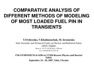
COMPARATIVE ANALYSIS OF DIFFERENT METHODS OF MODELING OF MOST LOADED FUEL PIN IN TRANSIENTS. Y.Ovdiyenko, V.Khalimonchuk, M. Ieremenko State Scientific and Technical Centre on Nuclear and Radiation Safety (SSTC N&RS) Stusa st. 35-37, 03142 Kyiv, Ukraine yn_ovdienko@sstc.kiev.ua

E N D
COMPARATIVE ANALYSIS OF DIFFERENT METHODS OF MODELING OF MOST LOADED FUEL PIN IN TRANSIENTS Y.Ovdiyenko, V.Khalimonchuk, M. Ieremenko State Scientific and Technical Centre on Nuclear and Radiation Safety (SSTC N&RS) Stusa st. 35-37, 03142 Kyiv, Ukraine yn_ovdienko@sstc.kiev.ua 17th SYMPOSIUM of AER on VVER Reactor Physics and Reactor Safety September24 - 28, 2007, Yalta, Ukraine
THREE METHODS OF MODELLING OF MOST LOADED FUEL PIN ARE CONSIDERED: • Pin-by-pin calculation by using of coupled codes DYN3D/DERAB; • power distribution reconstruction inside of fuel assembly • “hot channel” methodology used by DYN3D code. 17th SYMPOSIUM of AER, Yalta, Ukraine
PIN-BY-PIN CALCULATION BY USING OF COUPLED CODES DYN3D/DERAB: • Most accurate method of modelling of single fuel pin from among used in frame of the given work. • DERAB - fine-mesh finite-difference program intended for neutron flux calculation with two-group diffusion approximation in hexagonal fuel assembly cross-section with triangular fuel lattice. • Two-group neutron diffusion equation is solved in region composed of central assembly and six half of surrounding assemblies. • Fine-mesh calculation is performed with setting of boundary conditions from DYN3D code. • Pin burnup distribution is taking into account in every node by taking stock of history of previous fuel campaigns. • Requires too much resource. 17th SYMPOSIUM of AER, Yalta, Ukraine
POWER DISTRIBUTION RECONSTRUCTION: • neutron flux is reconstructed by an analytical solution of the two-dimensional diffusion equation in each layer of the assembly; • pin power reconstruction is performed on base of average value of fuel burnup in considered node that will cause some error during modelling of most loaded fuel pin “HOT CHANNEL” METHODOLOGY: • Axial power distribution for each “hot channel” is defined by multiplication of axial power distribution of average loaded pin of considered fuel assembly by some coefficient. • Axial profile of relative power of “hot channel” will be corresponding to profile of connected core channel. • Doesn’t allow determining change of position of most loaded element, and also change of axial and radial profiles inside of fuel assembly during transient. 17th SYMPOSIUM of AER, Yalta, Ukraine
INITIAL CONDITIONS: • reactor power corresponds to rated value 3000 MW; • beginning of the reactor campaign (most high power peeking factors) • working group of CPS control rods is located at position of Н10 =177 cm from bottom of core ( lowest regulation position); • temperature of coolant at inlet of core is 287С; • non-uniform equilibrium poisoning with Xe and Sm. • ejection of cluster from fuel assembly №85 for time 0.1s is considered in the presented transient. 17th SYMPOSIUM of AER, Yalta, Ukraine
Fig. 1 – Relative assembly powers (Kq) at the beginning of transient 17th SYMPOSIUM of AER, Yalta, Ukraine
Three fuel pins are considered : • most loaded fuel pin №266 of assembly №101; • peripheral fuel pin №266 of assembly №85, from which ejection of partial inserted cluster is considered; • fuel pin №206 of assembly №85, that situated near to inserted cluster. 17th SYMPOSIUM of AER, Yalta, Ukraine
Fig. 3 – Relative pin powers (Kr) at FA№101 at the beginning of transient 17th SYMPOSIUM of AER, Yalta, Ukraine
Fig. 2 – Relative pin powers (Kr) at FA№85 at the beginning of transient 17th SYMPOSIUM of AER, Yalta, Ukraine
Fig. 4 – Linear power at pin № 266 of assembly №101, t=0 17th SYMPOSIUM of AER, Yalta, Ukraine
Fig. 5 – Linear power at pin № 206 of assembly №85, t=0 17th SYMPOSIUM of AER, Yalta, Ukraine
Fig. 6 – Linear power at pin № 266 of assembly №85, t=0 17th SYMPOSIUM of AER, Yalta, Ukraine
Fig. 7 – Linear power at pin № 266 of assembly №101, t=0.1s 17th SYMPOSIUM of AER, Yalta, Ukraine
Fig. 8 – Linear power at pin № 206 of assembly №85, t=0.1s 17th SYMPOSIUM of AER, Yalta, Ukraine
Fig. 9 – Linear power at pin № 266 of assembly №85, t=0.1s 17th SYMPOSIUM of AER, Yalta, Ukraine
CONCLUSIONS • Significant differences of linear power calculation by use of “hot channel” and power reconstruction in comparison to pin-by-pin calculation are observed in the part of fuel assembly with inserted cluster. • In the part of fuel assembly without inserted cluster all three methods demonstrate the enough close results (3%) of axial linear power. • Underestimation ≈3% of the absolute value of linear power obtained by power reconstruction is observed, because microstructure of fuel assembly isn’t taken into account during flux reconstruction (namely presence of water gap). • Modeling with use of “hot channel” method is preferably for application for safety analysis of accidents with use of conservative approaches. This method gives more conservative results. • Model with use of power reconstruction, which partially takes into account deformation of power field inside of fuel assembly, is more applicable to so called «best estimated» calculations. But for this purpose it must be modified in part of taking into account of inner microstructure of fuel assembly and influence of spatial distribution of fuel pin burnup. 17th SYMPOSIUM of AER, Yalta, Ukraine