Download
1 / 37
370 likes | 382 Vues
Explore the KM3NeT project aiming to build a cubic-kilometer-scale neutrino telescope surpassing IceCube, study neutrino “point sources,” and address technical design challenges for a reliable, cost-effective deployment, and operation. Discover the project's objectives, implementation requirements, and research infrastructure.

E N D
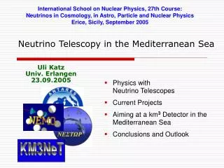
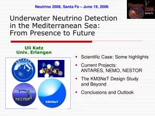
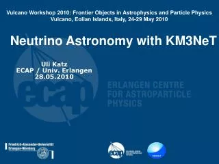
International School on Nuclear Physics, 32nd Course: Particle and Nuclear AstrophysicsErice, Sicily, 16–24 September 2010 Neutrino Astronomy with KM3NeTwas: Mediterranean Neutrino Telescopes - Status and Future Uli Katz ECAP / Univ. Erlangen 17.09.2010
Introduction • Technical solutions: Decisions and options • Physics sensitivity • Cost and implementation • Summary U. Katz: KM3NeT (Erice 2010)
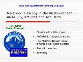
The Neutrino Telescope World Map ANTARES, NEMO, NESTORjoined efforts to preparea km3-size neutrino telescope in the Mediterranean SeaKM3NeT NEMO U. Katz: KM3NeT (Erice 2010)
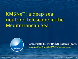
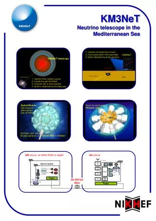
What is KM3NeT ? • Future cubic-kilometre scale neutrino telescope in the Mediterranean Sea • Exceeds Northern-hemisphere telescopes by factor ~50 in sensitivity • Exceeds IceCube sensitivity by substantial factor • Provides node for earth and marine sciences U. Katz: KM3NeT (Erice 2010)
South Pole and Mediterranean Fields of View 2p downward sensitivity assumed In Mediterranean,visibilityof givensource canbe limitedto less than 24h per day > 25% > 75% U. Katz: KM3NeT (Erice 2010)
The Objectives • Central physics goals: • Investigate neutrino “point sources” in energy regime 1-100 TeV • Complement IceCube field of view • Exceed IceCube sensitivity • Not in the central focus: • Dark Matter • Neutrino particle physics aspects • Exotics (Magnetic Monopoles, Lorentz invariance violation, …) • Implementation requirements: • Construction time ≤5 years • Operation over at least 10 years without “major maintenance” U. Katz: KM3NeT (Erice 2010)
Unique orpreferredsolutions Technical Design Objective: Support 3D-array of photodetectors andconnect them to shore (data, power, slow control) • Optical Modules • Front-end electronics • Readout, data acquisition, data transport • Mechanical structures, backbone cable • General deployment strategy • Sea-bed network: cables, junction boxes • Calibration devices • Shore infrastructure • Assembly, transport, logistics • Risk analysis and quality control Design rationale: Cost-effectiveReliableProducibleEasy to deploy U. Katz: KM3NeT (Erice 2010)
Further Challenges • Site characteristicsObjective: Measure site characteristics (optical background, currents, sedimentation, …) • SimulationObjective: Determine detector sensitivity, optimise detector parameters; • Earth and marine science nodeObjective: Design interface to instrumentation for marine biology, geology/geophysics, oceanography, environmental studies, alerts, … • ImplementationObjective: Take final decisions (technology and site), secure resources, set up proper management/governance, construct and operate KM3NeT; U. Katz: KM3NeT (Erice 2010)
The First-Generation Projects • ANTARES:See presentation by Thomas Eberl, today 18:00-18:30 • NEMO and NESTORMajor contributions to R&DSite exploration • All 3 have become part of KM3NeT U. Katz: KM3NeT (Erice 2010)
NEMO • Extensive site exploration(Capo Passero near Catania, depth 3500 m); • R&D towards km3: architecture, mechanical structures, readout, electronics, cables ...; • Simulation. Example: Flexible tower • ~10 m bar length,bars 30-40 m apart; • 3 pairs of PMs per bar • Unfurls after deployment as compact structure. U. Katz: KM3NeT (Erice 2010)
NESTOR • Tower based detector(titanium structures). • Dry connections(recover − connect − redeploy). • Up- and downward looking PMs (15’’). • 4000-5200 m deep. • Test floor (reduced size) deployed & operated in 2003.
NESTOR: the Delta-Berenike Platform • A dedicated deployment platform • In the final stage of construction • Can be important asset for KM3NeT deployment U. Katz: KM3NeT (Erice 2010)
The KM3NeT Research Infrastructure (RI) (DU) U. Katz: KM3NeT (Erice 2010)
OM “classical”: One PMT, no Electronics Evolution from pilot projects: • 8-inch PMT, increased quantum efficiency(instead of 10 inch) • 13-inch glass sphere(instead of 17 inch) • no valve(requires “vacuum”assembly) • no mu-metalshielding U. Katz: KM3NeT (Erice 2010)
OM with many Small PMTs 31 3-inch PMTs in 17-inch glass sphere (cathode area~ 3x10” PMTs) 19 in lower, 12 in upper hemisphere Suspended by compressible foam core 31 PMT bases (total ~140 mW) (D) Front-end electronics (B,C) Al cooling shield and stem (A) Single penetrator 2mm optical gel Advantages: increased photocathode area improved 1-vs-2 photo-electron separation better sensitivity to coincidences directionality A B C C D PMT X U. Katz: KM3NeT (Erice 2010)
Front-End Electronics: Time-over-Threshold From the analogue signal to time stamped digital data: t2 t3 t4 Time t1 t5 t6 … Threshold 1 Threshold 2 Amplitude Threshold 3 Analoguesignal Digitaldata Ethernet TCP/IPdata link Front End ASIC System onChip (SoC) Shore Scott chip FPGA+processor U. Katz: KM3NeT (Erice 2010)
Data Network • All data to shore:Full information on each hit satisfying local condition (threshold) sent to shore • Overall data rate ~ 25 Gbyte/s • Data transport:Optical point-to-point connection shore-OMOptical network using DWDM and multiplexingServed by lasers on shoreAllows also for time calibration of transmission delays • Deep-sea components:Fibres, modulators, mux/demux, optical amplifiers(all standard and passive) U. Katz: KM3NeT (Erice 2010)
DUs: Bars, Strings, Triangles Reminder: Progress in verifying deep-sea technology can be slow and painful Careful prototype tests are required before taking final decisions This is an ongoing task • Flexible towers with horizontal bars • Simulation indicates that “local 3D arrangement” of OMs increases sensitivity significantly • Single- or multi-PMT OMs • Slender strings with multi-PMT OMs • Reduced cost per DU, similar sensitivity per Euro • Strings with triangular arrangementsof PMTs • Evolution of ANTARES concept • Single- or multi-PMT OMs • “Conservative” fall-back solution U. Katz: KM3NeT (Erice 2010)
The Flexible Tower with Horizontal Bars • 20 storeys • Each storey supports 6 OMs in groups of 2 • Storeys interlinked by tensioning ropes, subsequent storeys orthogonal to each other • Power and data cables separated from ropes;single backbone cable with breakouts to storeys • Storey length = 6m • Distance between storeys = 40 m • Distance between DU base and first storey = 100m U. Katz: KM3NeT (Erice 2010)
Mooring line: Buoy (empty glass spheres, net buoyancy 2250N) Anchor: concrete slab of 1m3 2 Dyneema ropes (4 mm diameter) 20 storeys (one OM each),30 m distance, 100m anchor-first storey Electro-optical backbone: Flexible hose ~ 6mm diameter Oil-filled 11 fibres and 2 copper wires At each storey: 1 fibre+2 wires Break out box with fuses at each storey: Onesingle pressure transition Star network between master module and optical modules The Slender String New concept, needs to be tested. Also for flexible tower if successful U. Katz: KM3NeT (Erice 2010)
Triangle Structure 40 m 19X40 = 760 m 100 m • Evolution from ANTARES concept • 20 storeys/DU, spacing 40m • Backbone: electro-optical-mechanical cable • Reduced number of electro-optical penetrations • Use ANTARES return of experience 2.3m U. Katz: KM3NeT (Erice 2010)
Deployment Strategy • All three mechanical solutions:Compact package – deployment – self-unfurling • Eases logistics (in particular in case of several assembly lines) • Speeds up and eases deployment;several DUs can be deployed in one operation • Self-unfurling concepts need to be thoroughly tested and verified • Connection to seabed network by ROV • Backup solution: “Traditional” deployment from sea surface U. Katz: KM3NeT (Erice 2010)
A Flexible Tower Packed for Deployment Successful deployment test 12-14 Feb. 2010 U. Katz: KM3NeT (Erice 2010)
Compactifying Strings Slender string rolled upfor self-unfurling: 3 triangles Successful deployment test 16. Dec. 2009 DU U. Katz: KM3NeT (Erice 2010)
Hydrodynamic Stability d • DUs move under drag of sea current • Currents of up to 30cm/s observed • Mostly homogeneous over detector volume • Deviation from vertical at top: • Torsional stability also checked U. Katz: KM3NeT (Erice 2010)
2 km 2 km Detector Building Blocks } • Different DU designs • require different DU distance • differ in photocathode area/DU • are different in cost different„building blockfootprints“ Bars, triangle: 127 DUs, distance 180/150 m Footprint optimisation is ongoing Slender string: 310 DUs, distance 130 m U. Katz: KM3NeT (Erice 2010)
Optimisation Studies Example: Sensitivity dependence of point-source search on DU distance for flexible towers (for 2 different neutrino fluxes ~E- a, no cut-off) a = 2.2 a = 2.0 U. Katz: KM3NeT (Erice 2010)
Angular Resolution • Investigate distribution of angle between incoming neutrino and reconstructed muon • Dominated by kinematics up to ~1TeV kinematics < 0.1° U. Katz: KM3NeT (Erice 2010)
Effective Areas (per Building Block) • Results very similar for hard quality cuts • Flexible towers with bars and slender strings “in same ballpark” • Driven by overall photocathode area Symbols: Flexible towers, different quality cuts Lines: Slender lines, different quality cuts U. Katz: KM3NeT (Erice 2010)
Cost Estimates: Assumptions • Estimate of investment cost • no personnel costs included • no contingency, no spares • Assumptions / procedure: • Quotations from suppliers are not official and subject to change • Common items are quoted with same price • Sea Sciences and Shore Station not estimated • Estimates worked out independently by expert groups and carefully cross-checked and harmonised thereafter U. Katz: KM3NeT (Erice 2010)
Cost Estimates: Results • Result of cost estimates (per building block): • Assembly man power (OMs, DU…) is roughly estimated to be 10% of the DU cost U. Katz: KM3NeT (Erice 2010)
KM3NeT: Full Configuration • 2 “building blocks” needed to achieve objectives • Increases sensitivity by a factor 2 • Overall investment ~220 M€ • Staged implementation possible • Science potential from very early stage of construction on • Operational costs 4-6 M€ per year (2-3% of capital investment), including electricity, maintenance, computing, data centre and management U. Katz: KM3NeT (Erice 2010)
Point Source Sensitivity (1 Year) R. Abbasi et al. Astro-ph (2009) scaled – unbinned method Expected exclusion limits: Aharens et al. Astr. Phys. (2004) – binned method IceCube KM3NeT(binned) Observation of RXJ1713 with 5s within ~8 years Observed Galactic TeV-g sources (SNR, unidentified, microquasars) F. Aharonian et al. Rep. Prog. Phys. (2008) Abdo et al., MILAGRO, Astrophys. J. 658 L33-L36 (2007) U. Katz: KM3NeT (Erice 2010)
Candidate Sites • Locations of thethree pilot projects: • ANTARES: Toulon • NEMO: Capo Passero • NESTOR: Pylos • Long-term sitecharacterisationmeasurementsperformed • Site decision requiresscientific, technologicaland political input U. Katz: KM3NeT (Erice 2010)
Recent Developments • Convergence towards a bar structure with multi-PMT OMs:6m bars with 1 OM at each end • Prototyping of components under way • Simulation and “footprint” studies ongoing • Possible cooperation with IceCube being explored (towards a Global Neutrino Observatory) U. Katz: KM3NeT (Erice 2010)
Next Steps and Timeline • Next steps: Prototyping and design decisions • TDR public since June 2010 • final decisions require site selection • expected to be achieved in 15 months • Timeline: U. Katz: KM3NeT (Erice 2010)
Conclusions • A design for the KM3NeT neutrino telescope complementing the IceCube field in its of view and surpassing it in sensitivity by a substantial factor is presented. • Readiness for construction expected in 15 months • An overall budget of ~250 M€ will be required. Staged implementation, with increasing discovery potential, is technically possible. • Within 15 months, remaining design decisions have to be taken and the site question clarified. • Installation could start in 2013 and data taking soon after. U. Katz: KM3NeT (Erice 2010)