Download
1 / 56
560 likes | 573 Vues
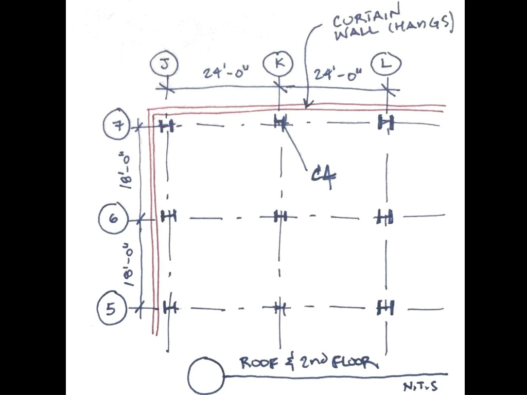
Roof Trib Area = 24’-0” x 9’-0” = 216 sqft DL = (90 psf)(216 sqft)/1000 = 19.44k LL = (20 psf) (216 sqft)/1000 = 4.32k CW = (15 psf)(24ft)(15ft)/1000 = 5.4k. 2 nd Floor Trib Area = 24’-0” x 9’-0” = 216 sqft DL = (100 psf)(216 sqft)/1000 = 21.6k LL = (100 psf) (216 sqft)/1000 = 21.6k

E N D
Roof Trib Area = 24’-0” x 9’-0” = 216 sqft DL = (90 psf)(216 sqft)/1000 = 19.44k LL = (20 psf) (216 sqft)/1000 = 4.32k CW = (15 psf)(24ft)(15ft)/1000 = 5.4k
2nd Floor Trib Area = 24’-0” x 9’-0” = 216 sqft DL = (100 psf)(216 sqft)/1000 = 21.6k LL = (100 psf) (216 sqft)/1000 = 21.6k CW = (15 psf)(24ft)(15ft)/1000 = 5.4k
DL 19.44k LL 4.32k CW 5.4k V P M Column C4 - 0 + - 0 + - 0 + -29.16k -77.76k DL 21.6k LL 21.6k CW 5.4k -77.76k - 0 + - 0 + - 0 +
WIND LOADS SEISMIC LOADS LATERAL LOAD FLOW FRAMES and SHEAR WALLS
Wind Loading W2 = 30 PSF W1 = 20 PSF
Wind Load spans to each level 1/2 LOAD W2 = 30 PSF SPAN 10 ft 1/2 + 1/2 LOAD SPAN 10 ft W1 = 20 PSF 1/2 LOAD
Total Wind Load to roof level wroof= (30 PSF)(5 FT) = 150 PLF
Total Wind Load to second floor level wsecond= (30 PSF)(5 FT) + (20 PSF)(5 FT) = 250 PLF
wroof= 150 PLF wsecond= 250 PLF
Determine Spectral Response Parameters at design location At 37.80 N , -122.37 W : Ss = 1.50 S1 = 0.60
Determine Site Coefficients Site Class : D Ss > 1.25 Fa = 1.0 S1 > 0.5 Fv = 1.5 Determine Design Spectral Acceleration Parameters SMS = (1.0)(1.5) = 1.5 SDS = (2/3)(1.5) = 1.0
Cs = SDS /(R/I) =1.0/(R/I) Class II : I = 1.0 Ordinary Moment Resisting Frame : R = 3.5 V = 1.0/3.5 W 0.3 W
Seismic Load is generated by the inertia of the mass of the structure : VBASE Redistributed (based on relative height and weight) to each level as a ‘Point Load’ at the center of mass of the structure or element in question : FX VBASE Wx hx S(w h) VBASE = (Cs)(W) ( VBASE ) Fx =
Total Seismic Loading : VBASE = 0.3 W W = Wroof + Wsecond
Redistribute Total Seismic Load to each level based on relative height and weight Froof Fsecond flr VBASE (wx)(hx) S (w h) Fx =
VBASE (wx)(hx) S (w h) Fx = In order to solve the equivalent lateral force distribution equation, we suggest you break it up into a spreadsheet layout Floor w h (w)(h) (w)(h)/S(w)(h) Vbase Fx Roof 166.67k 30ft 5000k-ft 0.625 110k 68.75k 2nd 200k 15ft 3000k-ft 0.375 110k 41.25k S (366.67k) S(8000k-ft) S (110k) Vbase = 0.3W = 0.3(166.67k+200k) = 0.3(366.67k) = 110k
Load Flow to Lateral Resisting System : Distribution based on Relative Rigidity Assume Relative Rigidity : Single Bay MF : Rel Rigidity = 1 2 - Bay MF : Rel Rigidity = 2 3 - Bay MF : Rel Rigidity = 3
Distribution based on Relative Rigidity : SR = 1+1+1+1 = 4 Px = ( Rx / SR ) (Ptotal) PMF1 = 1/4 Ptotal
Lateral Load Flow diaphragm > collectors/drags > frames
STRUCTURAL DIAPHRAGM A structural diaphragm is a horizontal structural system used to transfer lateral loads to shear walls or frames primarily through in-plane shear stress Basically, combined with vertical shear walls or frames IT ACTS LIKE A LARGE I-BEAM
STRUCTURAL DIAPHRAGM Flexible or Semi-flexible Type: Plywood Metal Decking
STRUCTURAL DIAPHRAGM Rigid Diaphragm Type: Reinforced Concrete Slab Concrete-filled Metal Deck composite Slab Braced/horizontal truss
STRUCTURAL DIAPHRAGM Rigid Diaphragm: Almost no deflection Can transmit loads through torsion Flexible Diaphragm: Deflects horizontally Cannot transmit loads through torsion
COLLECTORS and DRAG STRUTS A beam element or line of reinforcement that carries or “collects” loads from a diaphragm and carries them axially to shear walls or frames. A drag strut or collector behaves like a column.
COLLECTOR FRAME DIAPHRAGM COLLECTOR FRAME Lateral Load Flow diaphragm > collectors/drags > frames
COLLECTOR FRAME LATERAL LOAD (WIND) DIAPHRAGM COLLECTOR FRAME Lateral Load Flow diaphragm > collectors/drags > frames
COLLECTOR FRAME LATERAL LOAD DIAPHRAGM COLLECTOR FRAME Lateral Load Flow diaphragm > collectors/drags > frames
LATERAL LOAD COLLECTOR FRAME FRAME COLLECTOR DIAPHRAGM COLLECTOR COLLECTOR FRAME
LATERAL FORCE RESISTING SYSTEMS: MOMENT Resisting frames Diagonally BRACED frames SHEAR walls
INSTABILITY OF THE FRAME Pinned connectionscannot resist rotation.This is not a structurebut rather a mechanism.
STABILIZE THE FRAME FIX ONE OR MORE OF THE BASES
STABILIZE THE FRAME FIX ONE OR MORE OF THE CORNERS
STABILIZE THE FRAME ADD A DIAGONAL BRACE
RELATIVE STIFFNESS OF FRAMES AND WALLS LOW DEFLECTION HIGH STIFFNESS ATTRACTS MORE LOAD HIGH DEFLECTION LOW STIFFNESS ATTRACTS LESS LOAD