Understanding VLANs and PPP in Computer Networking**
This lecture covers the fundamentals of Virtual Local Area Networks (VLANs) and Point-to-Point Protocol (PPP) within the context of computer networks. Topics include the motivation behind VLANs, issues with single broadcast domains, and how VLANs enhance security and efficiency by allowing multiple virtual networks over a single physical infrastructure. The lecture also delves into PPP, its design requirements, frame structures, and error detection mechanisms, alongside practical insights into link-layer functionalities and configurations.

Understanding VLANs and PPP in Computer Networking**
E N D
Presentation Transcript
University of Nevada – Reno Computer Science & Engineering Department Fall 2011 CPE 400 / 600Computer Communication Networks Lecture 26 Link Layer (PPP, Virtualization) slides are modified from J. Kurose & K. Ross Introduction
VLANs: motivation What happens if: • CS user moves office to CE, but wants connect to CS switch? • single broadcast domain: • all layer-2 broadcast traffic (ARP, DHCP) crosses entire LAN • security/privacy, efficiency issues • each lowest level switch has only few ports in use What’s wrong with this picture? Computer Science Computer Engineering Electrical Engineering 5: DataLink Layer
7 1 2 8 15 9 10 16 VLANs Port-based VLAN: switch ports grouped (by switch management software) so that single physical switch …… 15 7 9 1 Virtual Local Area Network 2 8 10 16 … … Switch(es) supporting VLAN capabilities can be configured to define multiple virtual LANS over single physical LAN infrastructure. Computer Science (VLAN ports 9-15) Computer Engineering (VLAN ports 1-8) … operates as multiple virtual switches … … Computer Science (VLAN ports 9-16) Computer Engineering (VLAN ports 1-8) 5: DataLink Layer
forwarding between VLANS: done via routing • just as with separate switches • in practice vendors sell combined switches plus routers Port-based VLAN router • traffic isolation: frames to/from ports 1-8 can only reach ports 1-8 • can also define VLAN based on MAC addresses of endpoints, rather than switch port 15 7 9 1 2 8 10 16 • dynamic membership: ports can be dynamically assigned among VLANs … … Computer Science (VLAN ports 9-15) Computer Engineering (VLAN ports 1-8) 5: DataLink Layer
1 16 VLANS spanning multiple switches • trunk port: carries frames between VLANS defined over multiple physical switches • frames forwarded within VLAN between switches can’t be vanilla 802.1 frames (must carry VLAN ID info) • 802.1q protocol adds/removed additional header fields for frames forwarded between trunk ports 15 7 9 7 1 3 5 2 8 10 4 6 2 8 … … Computer Science (VLAN ports 9-15) Ports 2,3,5 belong to CE VLAN Ports 4,6,7,8 belong to CS VLAN Computer Engineering (VLAN ports 1-8) 5: DataLink Layer
Type 802.1Q VLAN frame format 802.1 frame 802.1Q frame 2-byte Tag Protocol Identifier (value: 81-00) Recomputed CRC Tag Control Information (12 bit VLAN ID field, 3 bit priority field like IP TOS) 5: DataLink Layer
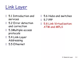
5.1 Introduction and services 5.2 Error detection and correction 5.3Multiple access protocols 5.4 Link-Layer Addressing 5.5 Ethernet 5.6 Link-layer switches 5.7 PPP 5.8 Link virtualization: MPLS Link Layer 5: DataLink Layer
Point to Point Data Link Control • one sender, one receiver, one link: easier than broadcast link: • no Media Access Control • no need for explicit MAC addressing • e.g., dialup link, ISDN line • popular point-to-point DLC protocols: • PPP: point-to-point protocol • HDLC: High level data link control • Data link used to be considered “high layer” in protocol stack! 5: DataLink Layer
PPP Design Requirements [RFC 1557] • packet framing: encapsulation of network-layer datagram in data link frame • carry network layer data of any network layer protocol (not just IP) at same time • ability to demultiplex upwards • bit transparency: must carry any bit pattern in the data field • error detection (no correction) • connection liveness: detect, signal link failure to network layer • network layer address negotiation: endpoint can learn/configure each other’s network address 5: DataLink Layer
PPP non-requirements • no error correction/recovery • no flow control • out of order delivery OK • no need to support multipoint links (e.g., polling) Error recovery, flow control, data re-ordering all relegated to higher layers! 5: DataLink Layer
PPP Data Frame • Flag: delimiter (framing) • Address: does nothing (only one option) • Control: does nothing; • in the future possible multiple control fields • Protocol: upper layer protocol to which frame delivered • eg, PPP-LCP, IP, IPCP, etc 5: DataLink Layer
PPP Data Frame • info: upper layer data being carried • check: cyclic redundancy check for error detection 5: DataLink Layer
Byte Stuffing • “data transparency” requirement: data field must be allowed to include flag pattern <01111110> • Q: is received <01111110> data or flag? • Sender: adds (“stuffs”) extra < 01111101> byte before each < 01111110> data byte • Receiver: • discard first byte, continue data reception • single 01111110: flag byte 5: DataLink Layer
Byte Stuffing flag byte pattern in data to send flag byte pattern plus stuffed byte in transmitted data 5: DataLink Layer
PPP Data Control Protocol Before exchanging network-layer data, data link peers must • configure PPP link • max. frame length, authentication • learn/configure network layer information • for IP: carry IP Control Protocol (IPCP) msgs to configure/learn IP address 5: DataLink Layer
5.1 Introduction and services 5.2 Error detection and correction 5.3Multiple access protocols 5.4 Link-Layer Addressing 5.5 Ethernet 5.6 Link-layer switches 5.7 PPP 5.8 Link virtualization: MPLS Link Layer 5: DataLink Layer
Virtualization of networks Virtualization of resources: powerful abstraction in systems engineering: • computing examples: virtual memory, virtual devices • Virtual machines: e.g., java • IBM VM os from 1960’s/70’s • layering of abstractions: don’t sweat the details of the lower layer, only deal with lower layers abstractly 5: DataLink Layer
The Internet: virtualizing networks … differing in: • addressing conventions • packet formats • error recovery • routing 1974: multiple unconnected nets • ARPAnet • data-over-cable networks • packet satellite network (Aloha) • packet radio network satellite net ARPAnet "A Protocol for Packet Network Intercommunication", V. Cerf, R. Kahn, IEEE Transactions on Communications, May, 1974, pp. 637-648. 5: DataLink Layer
Internetwork layer (IP): • addressing: internetwork appears as single, uniform entity, despite underlying local network heterogeneity • network of networks The Internet: virtualizing networks Gateway: • “embed internetwork packets in local packet format or extract them” • route (at internetwork level) to next gateway gateway satellite net ARPAnet 5: DataLink Layer
Cerf & Kahn’s Internetwork Architecture What is virtualized? • two layers of addressing: internetwork and local network • new layer (IP) makes everything homogeneous at internetwork layer • underlying local network technology • cable • satellite • 56K telephone modem • today: ATM, MPLS … “invisible” at internetwork layer. Looks like a link layer technology to IP! 5: DataLink Layer
ATM and MPLS • ATM, MPLS separate networks in their own right • different service models, addressing, routing from Internet • viewed by Internet as logical link connecting IP routers • just like dialup link is really part of separate network (telephone network) • ATM, MPLS: of technical interest in their own right 5: DataLink Layer
Asynchronous Transfer Mode: ATM • 1990’s/00 standard for high-speed • 155Mbps to 622 Mbps and higher • Broadband Integrated Service Digital Network architecture • Goal:integrated, end-end transport of carry voice, video, data • meeting timing/QoS requirements of voice, video • versus Internet best-effort model • “next generation” telephony: technical roots in telephone world • packet-switching using virtual circuits • fixed length packets, called “cells” 5: DataLink Layer
Multiprotocol label switching (MPLS) • initial goal: speed up IP forwarding by using fixed length label (instead of IP address) to do forwarding • borrowing ideas from Virtual Circuit (VC) approach • but IP datagram still keeps IP address! PPP or Ethernet header IP header remainder of link-layer frame MPLS header label Exp TTL S 5 1 3 20 5: DataLink Layer
MPLS capable routers • a.k.a. label-switched router • forwards packets to outgoing interface based only on label value (don’t inspect IP address) • MPLS forwarding table distinct from IP tables • signaling protocol needed to set up forwarding • RSVP-TE • forwarding possible along paths that IP alone would not allow (e.g., source-specific routing) !! • use MPLS for traffic engineering • must co-exist with IP-only routers 5: DataLink Layer
in out out label labeldest interface 10 6 A 1 12 9 D 0 in out out label labeldest interface in out out label labeldest interface 8 6 A 0 6 - A 0 MPLS forwarding tables in out out label label dest interface 10 A 0 12 D 0 8 A 1 R4 R3 R6 0 0 D 1 1 R5 0 0 A R2 R1 5: DataLink Layer
principles behind data link layer services: error detection, correction sharing a broadcast channel: multiple access link layer addressing instantiation and implementation of various link layer technologies Ethernet switched LANS, VLANs PPP virtualized networks as a link layer: MPLS Chapter 5: Summary 5: DataLink Layer