Download
1 / 16
160 likes | 279 Vues
A Label-switching Packet Forwarding Architecture for Multi-hop Wireless LANs. Stanford University. IBM TJ Watson Research Center. 54. 22. 11. Motivation : Future of multi-hop WLANs. Emergence of high-speed and variable rate WLANs 1,2,..,11, ..,22, ..,54, 108 Mbps

E N D
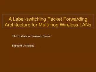
A Label-switching Packet ForwardingArchitecture for Multi-hop Wireless LANs Stanford University IBM TJ Watson Research Center
54 22 11 Motivation : Future of multi-hop WLANs • Emergence of high-speed and variable rate WLANs • 1,2,..,11, ..,22, ..,54, 108 Mbps • Larger bit-rate smaller coverage area • Multi-hop architecture for fixed wireless networks • Start with a large cell; as nodes increase split into (higher rate) smaller cells • Multi-hop wireless path to wireline gateway • Much of current work in ad-hoc networks on routing protocols and (single-cell) MAC • Efficient packet forwarding has not been studied : focus of this paper
A C B C A B Motivation (contd.) • A wireline router requires at least two network interfaces for packet forwarding • A router is a specialized node • A wireless node can forward packets with a single network interface card (NIC) Node B can reach both nodes A and C using the same wireless interface (Nodes A and C out of range of each other) Any intermediate nodein a multi-hop wireless network can operate as a router • wide-applicability for a packet forwarding architecture
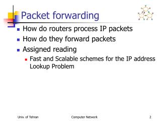
Timer Expiry Upstream Transfer Transfer packet to host for IP route lookup DATA A DIFS DATA RTS RTS B CTS ACK DIFS C ACK CTS Downstream Transfer Background : Packet Forwarding using 802.11 DCF • Channel access by upstream node A (RTS/CTS/ DATA/ACK) • Receive packet at node B’s network interface card • Transfer packet from NIC to host memory • Remove MAC header • Lookup route, next hop IP/MAC address • Add new MAC header (destination address C) • Transfer packet from host memory to NIC • Channel access by node B (RTS/CTS/DATA/ACK) What is a good architecture for packet forwarding ?
Our contribution : Efficient packet forwarding • Architecture for packet forwarding in wireless nodes • Address lookup using a table of labels in the NIC • Fixed-length labels enable exact matching, simple implementation • Packet forwarding entirely within the NIC Avoids packet transfer to/from host • Enhanced 802.11 DCF MAC : combines upstream and downstream channel accesses • A new ACK/RTS MAC control packet • ACK/RTS carries a label • Performance study via simulation host bus NIC
L1 IP pkt MACB MACc MACc L2 L2 IP pkt IP pkt Label switching : conceptual operation C A Dest Next-hop Label C B L1 B host input output L2 host input output L1 L2 MACC NIC NIC NIC
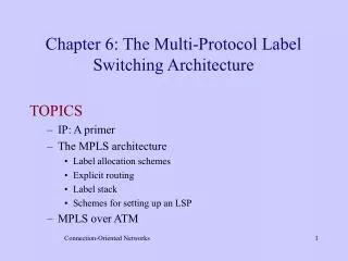
Routing Protocol Label Distribution Protocol ARP IP address (route entry) MAC addr (next hop) Label NIC/ Host support for label switching • A label-switching table in the NIC • Enables packet fwd’ing at an intermediate node’s NIC • Table populated by a label distribution protocol in the host • Similar to use of MPLS (multi-protocol label switching) in wired core networks • Maps routes/destinations to labels • First node labels packet based on destination IP Host Network Interface packet queue packet buffer packet mac label MAC processing NAV Data Packet Transfer INPUT Label OUTPUT MAC Label Label switching table Radio
SIFS DATA DATA DATA A R C T K S A R C T K S T MAC address ACK Flag (out) Label RTS Flag MAC address ACK/RTS control packet Enhancements to the 802.11 MAC • Forwarding node (B) combines ACK to upstream (A) with RTS to downstream node (C) • New ACK/RTScontrol packet • Include a label in the ACK/RTS corresponding to the final destination • Allows receiver to determine next-hop : lookup label-switching table in the NIC • Eliminates the need for a host-based route lookup T T R T S A C T S B CT S C C TS D DATA DRIVEN CUT-THROUGH MAC (DCMA)
DATA A R C T K S MAC enhancements : observations • ACK/RTS packet receives preferential access • channel reserved for T via CTS • neighborhood of B silent till end of ACK • Can cut-through over multiple hops if channel is free • No need to sense channel for downstream access for DIFS + timer • Downstream node (C) may deny CTS • fall back on base 802.11 • independent transfer from B to C R T S A CT S B T C TS C
Throughput vs Packet Size 400 300 Throughput (Kbps) 200 100 0 256 512 1024 1536 Data Packet Size (Bytes) 802.11 DCMA Simulated Performance of DCMA vs 802.11 • Result shown on a 7-hop chain • Significant reduction in latency • Data transfer overhead between NIC and host not included • Real results should be even more striking. Latency vs Packet Size 3 2 End-to-End Latency (s) 1 0 256 512 1024 1536 Data Packet Size (Bytes)
802.11 DCMA Results on a 4x4 grid • DCMA offers a flow preferential access • Links suffering from high interference (inner nodes) experience less performance degradation. • Inner rows gain at the expense of outer row fairer throughput distribution. Grid: Throughput (Kbps) Grid: End-to-End Latency (secs) 600 8 7 500 6 400 5 4 300 3 200 2 100 1 0 0 Column 1 Column 2 Column 3 Column 4 Column 1 Column 2 Column 3 Column 4
Summary • An architecture for packet forwarding by intermediate nodes • Packet forwarding accomplished within the NIC • Host to NIC transfers avoided • Components of the architecture • MAC enhancement : combine ACK and RTS • Use label-switching • Destinations/routes mapped to labels • ACK/RTS carries label • A label-switching table in the NIC (incoming label) (outgoing label, next-hop MAC address) • Current work : extending 802.11 DCF to allow simultaneous transmissions in neighboring cells S1 R1 S1 R1 S2 R2 R2 S2
Backup 1: DCMA Performance with Varying Transmission Rates (12 hop chain) • Effect of contention between intra-flow packets is reduced in DCMA. • Packets move along faster and thus compete less with each other. • DCMA throughput saturates at a higher value of offered load.
Backup 2: Simulation Details • 2Mbps channel, 550 meters interference range, 250 meters transmission range. • Node buffer size of 50 packets. • Grid distance = 250 meters diagonal nodes (425 meters) interfere with one another. • Increase in RTS_TIME and CTS_TIME values; no need to change DIFS or SIFS specifications. • DCMA suffers slower performance degradation as number of hops increases on the path.
SIFS SIFS Timer expiry DIFS R T S DATA A C T S A C K B SIFS Time 802.11 DCF MAC 802.11 DCF MAC • Four phases • Request to send (RTS) • Clear to send (CTS) • DATA packet • Acknowledgement (ACK)
data RTS • Fundamental constraint : a recvr should not be within range of >1 transmitter CTS P Q A B ack (1) (1) P P Q Q (2) (2) A B Q P (3) (3) (4) (4) B B A A MACA-P : Limitations of 802.11 MAC • Distributed ad-hoc mode of 802.11 MAC based on RTS(request-to-send) / CTS (clear-to-send) : MACA proposal (Karn) • Neighborhoods of both sender and recvr blocked out A B Q P B Q time MACA-P : Can MACA be enhanced to allow parallel transmissions?