Mingsheng Wei
Benchmark Modeling of Electron Beam Transport in Nail and Wire Experiments Using Three Independent PIC Codes. Center For Energy Research University of California, San Diego. Voss Scientific. RAC. Mingsheng Wei. FSC. Annual Fusion Science Center Meeting August 4-5, 2007 San Diego.

Mingsheng Wei
E N D
Presentation Transcript
Benchmark Modeling of Electron Beam Transport in Nail and Wire Experiments Using Three Independent PIC Codes Center For Energy Research University of California, San Diego Voss Scientific RAC Mingsheng Wei FSC Annual Fusion Science Center Meeting August 4-5, 2007 San Diego This work was supported by the US Dept of Energy through various grants from the Office of Fusion Energy Sciences.
D. Hey Lawrence Livermore National Laboratory Collaborators J. Pasley, T. Ma, J. King, E. Shipton, F.N. Beg R.B. Stephens A. Solodov RAC Y. Sentoku R. Mason D.R. Welch R.R. Freeman, L.Van Woerkom, D. Offerman, K. Highbarger, R. Weber M.H. Key, A.J. MacKinnon, A. MacPhee, S. Le Pape, P. Patel, S. Wilks
Outline • Motivation • Benchmark experiments using novel nail and wire targets • Codes used • Simulation results • Summary and future work
10nc 1000nc 40µm Guiding cone Fast electrons 5000nc 500nc High intensity laser 100’s µm High intensity laser ~ 50 µm Electron transport is a key issue for fast ignition MeV electrons have to propagate through 10’s to 100’s µm to heat the compressed fuel Density gradient in conventional FI via hole boring Density gradient in cone guided FI • Details of transport of fast electrons with huge currents remains uncertain • Numerical simulations help to understand instabilities, electron beam spreading, energy loss and heating mechanisms etc. in the transport process
We need a simple experiment to validate transport codes • Full scale modeling is impossible • Simulations are descriptive Modeling • hydro code to model the preformed plasma • hybrid PIC codes to study the electron transport Simulations Benchmark simulations against a simple experiment to validate the algorithms and transport models used in the codes Experiments • using simple target geometry • known laser parameters • well-characterized preformed plasmas • millimeter scale target • ps short pulse with ns pedestal Experiments
Benchmark experiments using low mass wire targetshave been performed on the Titan laser at LLNL Simple Ti wire: 50 µm in diameter Cu nail target Head:100 µm diameter Wire: 20 µm diameter with 2 µm Ti coating on the surface to examine surface vs. bulk transport Titan Laser parameters: Energy ~ 130 J Pulse length ~ 500 fs Spot size ~ 10 µm Peak intensity ~ 1020 W/cm2 • Wire targets are accessible to various diagnostics • Targets are small enough to be included in the simulations • K imagers diagnose the production and transport of the fast electrons • XUV imagers provide information of target heating
100 µm 100 µm 8.0 keV 4.5 keV Long range surface heating Cu K emission from the bulk Ti K emission from the surface 68 eV XUV Typical experimental observations ~800um 1 mm • Energy concentrated in the nail head • Limited propagation lengths along the wire • Long range plasma thermal emissions from the wire surface
We aim to accurately model the wire experiments • That means modeling the experiment as fielded, in addition to properly simulating the physics: - Target geometry - Preformed plasma produced by the nanosecond prepulse - Physically generate current - Direct comparison with the experimental data
Preformed plasma is modeled by the 2D hydro code h2d h2d simulation results Critical surface (on axis) the measured prepulse profile of the Titan short pulse laser Initial target surface Ne~1020 cm-3 (on axis) • Laser prepulse creates substantial preformed plasma, i.e., critical surface has moved away from original target surface by ~ 30 µm • Such preformed plasmas are included in the hybrid simulations
laser 13.3 vg/c -13.3 300 X(mm) 0 Fast electrons are trapped near the interaction region LSP e-PLAS Z (µm) 0 100 200 300 400 0 10 20 30 R (µm) trapping near critical by intense B-fields hot e- phase space Initial interface of kinetic electrons and fluid electrons R = 1 µm R = 7.6 µm R = 25 µm
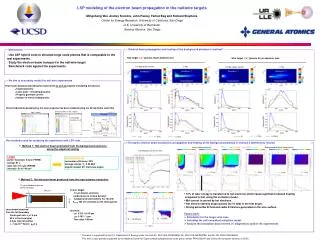
1023 1022 1021 1020 1019 1018 Number density (cm-3) Fast electrons have a overall limited propagation length of ~ 100 µm - 200 µm LSP e-PLAS PICLS 0 100 200 300 400 Z (µm) on-axis e- energy density • In both LSP and e-PLAS, nehot drops to 1020cm-3 in a distance of ~ 100 µm • In PICLS, electron energy density decreases by more than one order of magnitude in about 200 µm (this difference could be due to a lower e- number density used in the simulations)
1000 100 Temperature (eV) 0 100 200 300 400 Z (µm) 100 500 1000 Temperature (eV) Long range surface currents and the resultant surface heating have been observed in simulations PICLS LSP higher Tc on surface e-PLAS near axis at surface • At a greater distance, the wire surface is heated more than the inside due to the ohmic heating by the surface current • Pronounced surface heating in PICLS simulations
Z (µm) 0 200 400 0 10 20 30 40 50 Z (µm) 0 200 400 R (µm) -30 B (MG) 30 -40 B (MG) 40 - 1.5e7 Er (kV/cm) 1.5e7 Strong electric and magnetic fields are observed LSP laser • Surface radial E field : MV/µm • Surface azimuthal B field: 10’s MG in LSP 100 - 200 MG in e-PLAS • E&B fields are consistent with surface transport • Intense azimuthal B field is also produced at the deformed interaction region e-PLAS BZ (MG) -400 0 400 BZ contours
SUMMARY • Benchmark simulations using implicit/hybrid PIC codes, LSP and e-PLAS as well as the fully PIC code, PICLS, have been performed to study the fast electron beam transport in the nail/wire experiments • Simulations have shown good qualitative agreement among the codes, which are also in consistent with the experiments: • Localized energy deposition due to trapping of the fast electrons by B-fields. • Overall propagation length of about 100 µm in the bulk of the target predominantly due to resistive inhibition and B-field trapping at the interaction region • Long range surface current and surface heating • Intense surface E & B fields which guide the surface current • Quantitative differences are also observed: – Higher degree target heating in PICLS --- a lower density being used – Pronounced surface current (?) in PICLS --- a lower density being used – e-PLAS predicts extremely high surface B-fields (200 MG) – Low temperature in LSP due to the low laser energy in the input.
On-going and future work using the LSP code • Calculate K production and transport using the ITS code coupled to LSP • Analyze the simulation results in terms of diagnostics • Use more accurate EOS models to obtain background temperatures (currently, ideal gas model for all three codes, temperatures over estimated) • Continue the integrated LSP simulations to studyshort-pulse hot electron driven heating experiments using low-mass targets • Model electron beam transport and target heating in Omega EP FI experiments
Fast electrons produced in the latest integrated LSP simulations have a two-temperature energy distribution • >40% of the laser energy is transferred to the fast electrons • Average energy in the hot tail is comparable to the ponderomotive energy • The not-so-hot component fits to an average energy of 0.5 - 1 MeV
50 µm 450 µm Integrated LSP simulation setup #5 18th Sept #3 18th Sept • E-M wave is launched from the boundary • Energetic electrons are self-consistently produced from laser plasma interaction (LPI) • Solid wire targets are treated as fluid background. 0ns 3.5ns E-M wave from boundary Fluid electrons and ions PIC (kinetic) electrons and ions #5 14th Sept 7ns Ti wire: z=15, ne=8.451023 cm-3, initial temperature 100 eV • Ipeak ~ 71019 W/cm2 • = 0.5 PS (FWHM) =15 µm Simulation box 15 µm thick preformed plasma (1020 - 51022 cm-3)
PICLS 2D simulation setup • Laser (Titan):a=8, I=6.4•1019 W/cm2, pulse length=500 fs (gaussian)spot=20um (gaussian), Energy input=130 J • Target: nail target, Z=15, Cuion density=4•1022 1/cm3, e- density=6•1023 1/cm3wire diameter=20umpreplasma (5µm scale length, 1020-22 1/cm3) at top of nail • System size: 400um x 100um Ion energy density (n/n0): 1eV-100keV t=1.5ps
e-PLAS simulation setup • Laser: I=1.7 x 10²⁰ W/cm2, 1 ps pulse (top hat), 10 µm spot • Target: copper wire (z=15) preceded with a 20 µm density • ramp; initial temperature 100 eV • Electron beam generation: hot electrons are promoted from the critical surface with an isotropic Maxwellian spectrum at ponderomotive energies ( = 10.5) • System size: 100 µm by 300 µm
2D LSP simulations using the excitation model for fast electron generation without the preformed plasma Laser: 81 J, I = 51019 W/cm2, gaussian pulse 0.5 ps (fwhm), focal spot size 16.4 µm (fwhm) Fast Electron Density – Plasma Temperature at 1.5 ps Cu15+ nail target • Energy concentrated in the nail head • Surface current and resultant surface heating • Surface E and B fields r=0 r=10 µm r=7 µm