Download
1 / 11
110 likes | 302 Vues
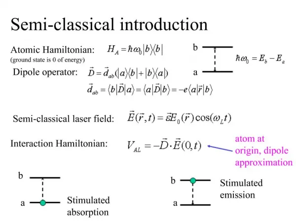
Quantum and semi-classical transport in RTDs using NEMO 1-D. Gerhard Klimeck Jet Propulsion Laboratory, California Institute of Technology gekco@jpl.nasa.gov (818) 354 2182 http://hpc.jpl.nasa.gov/PEP/gekco

E N D
Quantum and semi-classical transport in RTDs using NEMO 1-D Gerhard Klimeck Jet Propulsion Laboratory, California Institute of Technology gekco@jpl.nasa.gov (818) 354 2182 http://hpc.jpl.nasa.gov/PEP/gekco This research was carried out by at the Jet Propulsion Laboratory, California Institute of Technology under a contract with the National Aeronautics and Space Administration.
20/50/ 2 Software Engineering Object-Oriented Principles Documentation Tool Resonance Finder Physics Phonons Ionized Dopants Charging Formalism Green Function Theory & Boundary Cond. Material Param. Database Novel Grid Gen. Alloy Disorder Band- structure Interface Roughness Graphical User Interface Hybrid C, FORTRAN FORTRAN90 Testmatrix Library of Examples Batch Run Interface NEMO 1-D:A User-friendly Quantum Device Design Tool Good News! I mean great news! After 5 years of agony with Raytheon release problems: JPL can release the code to US institutions with a US government contract that requires / would benefit from NEMO use! • NEMO was developed under a government contract to Texas Instruments and Raytheon from 1993-97 • >50,000 person hours of R&D • 250,000 lines of code in C, FORTRAN and F90 • NEMO 1-D maintained and NEMO 3-D developed at JPL ‘98-’02 (>12,000 person hours) under NASA funding. Since ‘02 NSA and ONR funding. • Based on Non-Equilibrium Green function formalism • NEMO in THE state-of-the-art heterostructure design tool. • Used at Universities, Government Labs, Industry. • Bridges gap between device engineering and quantum physics. Transport/ Engineering Quantum Mechanics / Physics er
Density of States right reservoir left reservoir NEMO Breakthrough:Simulations of Devices With Realistic Large Extent • Quantum Optical Switch • Calculate charge self-consistently in • the left and right reservoir • central device region
Generalized Boundary Conditions:Boundaries as a Scattering Problem Three Critical Simulation Domains:left reservoir, central device, right reservoir Dynamics Kinetics How good is the reservoir assumption? Flat Fermi Level -> Zero Current
Couple NEGF in Central Device toDrift-Diffusion Equation in Reservoirs • Central Device • Carriers injected from reservoirs , need Fermi level in left/right edge • Fermi level not defined in central device. • Current / Charge from NEGF • Current imposed on reservoirs • Reservoirs: • Current imposed by central device • Gradient of Fermi level at each site imposed by current. • Charge from EGF and Fermi level • Self-consistency: • Poisson • NEGF • Drift-Diffusion
Current Voltage Characteristic • Compare µ=infinite, µ=20,000cm2/Vs, µ=10cm2/Vs • Low mobility -> similar to series resistance Vapplied = Vinternal+R I->stretch of voltage axis -> bi-stability
“Resistance” is not Constant! • Compare µ=infinite, µ=20,000cm2/Vs, µ=10cm2/Vs • Low mobility -> similar to series resistance Vapplied = Vinternal+R I->stretch of voltage axis -> bi-stability
Peak Current Depends Weakly on Mobility • Compare µ=infinite, µ=20,000cm2/Vs, µ=10cm2/Vs • Low mobility -> similar to series resistance Vapplied = Vinternal+R I->stretch of voltage axis -> bi-stability
High Mobility V=0.32V • µ=20,000cm2/Vs • Potential difference only in the quantum well. • High current state -> charge accumulation in well • Low current state -> empty quantum well
Low Mobility V=0.35V • µ=10cm2/Vs • Potential difference in emitter and quantum well. • High current state -> charge accumulation in well • Low current state -> empty quantum well, accumulation in notch
Comparison to Experiment & Conclusions Experiment: • Show I-V curves from two different devices from different wafers-> 15% peak current deviation • Introduction of finite mobility has small effect on overall I-V curve for high performance RTDs Conclusion: • Demonstrated coupling of drift diffusion to NEGF simulation. • Flat Fermi levels in reservoirs a pretty reasonable assumption. Future work: • Need to combine the intrinsic resistance simulation with a quantum capacitance calculation • Need to look at low performance RTDs with long spacer layers and low carrier densities.