Arithmetic
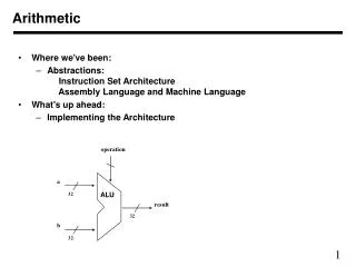
This article provides an in-depth overview of the arithmetic operations related to signed numbers, including addition and subtraction using full adders. We discuss the carry-in and carry-out mechanisms, the functioning of n-bit adders, and the propagation of carries through blocks. The concept of 2's complement for handling subtraction and overflow detection in binary addition is also covered. Additionally, the fast addition methods using carry lookahead and the structure of blocked carry-lookahead adders are examined, explaining their significance in digital computing.


Arithmetic
E N D
Presentation Transcript
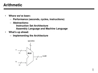
Addition/subtraction of signed numbers At the ith stage: Input: ci is the carry-in Output: si is the sum ci+1 carry-out to (i+1)st state x y Carry-in c Sum s Carry-out c i i i i i +1 0 0 0 0 0 0 0 1 1 0 0 1 0 1 0 0 1 1 0 1 1 0 0 1 0 1 0 1 0 1 1 1 0 0 1 1 1 1 1 1 x y c + x y c + x y c + x y c s = = x Å y Å c i i i i i i i i i i i i i i i i y c x c x y c = + + i i i i i i i +1 E xample: x X 7 0 1 1 1 Carry-out Carry-in i y + Y = + 6 = + 0 1 1 0 0 1 1 0 0 c i c i +1 i 13 1 1 0 1 s Z i Legend for stage i
y i c i x i x i c y s c i i i + 1 i c i x x y i i i y i Addition logic for a single stage Sum Carry Full adder c c i + 1 i (F A) s i Full Adder (FA): Symbol for the complete circuit for a single stage of addition.
x y x y x y n - 1 n - 1 1 1 0 0 c c n - 1 1 c c F A F A F A n 0 s s s n - 1 1 0 Most significant bit Least significant bit (MSB) position (LSB) position n-bit adder • Cascade n full adder (FA) blocks to form a n-bit adder. • Carries propagate or ripple through this cascade, n-bit ripple carry adder. Carry-in c0 into the LSB position provides a convenient way to perform subtraction.
K n-bit adder K n-bit numbers can be added by cascading kn-bit adders. x y x y x y x y x y k n - 1 k n - 1 2 n - 1 2 n - 1 n n n - 1 n - 1 0 0 c n n - bit n - bit n - bit c c adder adder adder 0 k n s s s s s s ( ) k n - 1 k - 1 n 2 n - 1 n n - 1 0 Each n-bit adder forms a block, so this is cascading of blocks. Carries ripple or propagate through blocks, Blocked Ripple Carry Adder
x y x y x y n - 1 n - 1 1 1 0 0 c c n - 1 1 c F A F A F A 1 n s s s n - 1 1 0 Most significant bit Least significant bit (MSB) position (LSB) position n-bit subtractor • Recall X – Y is equivalent to adding 2’s complement of Y to X. • 2’s complement is equivalent to 1’s complement + 1. • X – Y = X + Y + 1 • 2’s complement of positive and negative numbers is computed similarly.
n-bit adder/subtractor (contd..) y y y n - 1 1 0 Add/Sub control x x x n - 1 1 0 n -bit adder c n c 0 s s s n - 1 1 0 • Add/sub control = 0, addition. • Add/sub control = 1, subtraction.
Detecting overflows • Overflows can only occur when the sign of the two operands is the same. • Overflow occurs if the sign of the result is different from the sign of the operands. • Recall that the MSB represents the sign. • xn-1, yn-1, sn-1 represent the sign of operand x, operand y and result s respectively. • Circuit to detect overflow can be implemented by the following logic expressions:
y0 x0 FA c1 c0 s0 Computing the add time Consider 0th stage: • c1 is available after 2 gate delays. • s1 is available after 1 gate delay. Carry Sum y i c i x i x i c y s c i i i + 1 i c i x i y i
y0 x0 y0 x0 y0 y0 x0 x0 FA FA FA FA c0 c1 c2 c3 c4 s0 s1 s3 s2 Computing the add time (contd..) Cascade of 4 Full Adders, or a 4-bit adder • s0 available after 1 gate delays, c1 available after 2 gate delays. • s1 available after 3 gate delays, c2 available after 4 gate delays. • s2 available after 5 gate delays, c3 available after 6 gate delays. • s3 available after 7 gate delays, c4 available after 8 gate delays. For an n-bit adder,sn-1is available after 2n-1 gate delays cnis available after2ngate delays.
Fast addition Recall the equations: Second equation can be written as: We can write: • Giis called generate function andPiis called propagate function • Gi and Pi are computed only from xiand yi and not ci, thus they can • be computed in one gate delay after X and Y are applied to the • inputs of an n-bit adder.
Carry lookahead • All carries can be obtained 3 gate delays afterX, Yandc0are applied. • -One gate delay for Pi and Gi • -Two gate delays in the AND-OR circuit for ci+1 • All sums can be obtained 1 gate delay after the carries are computed. • Independent of n, n-bit addition requires only 4 gate delays. • This is called Carry Lookahead adder.
Carry-lookahead adder x y x y x y x y 3 3 2 2 1 1 0 0 . 4-bit carry-lookahead adder c c c c 3 2 1 c B cell B cell B cell B cell 4 0 s s s s 3 2 1 0 G P G P G P G P 0 0 3 3 2 2 1 1 Carry-lookahead logic y x i i . . . c i B cell B-cell for a single stage G P s i i i
c = G + P G + P P G + .. + P P .. P G + P P ... P c0 + - - - - - i 1 i i i 1 i i 1 i 2 i i 1 1 0 i i 1 0 Carry lookahead adder (contd..) • Performing n-bit addition in 4 gate delays independent of n is good only theoretically because of fan-in constraints. • Last AND gate and OR gate require a fan-in of (n+1) for a n-bit adder. • For a 4-bit adder (n=4) fan-in of 5 is required. • Practical limit for most gates. • In order to add operands longer than 4 bits, we can cascade 4-bit Carry-Lookahead adders. Cascade of Carry-Lookahead adders is called Blocked Carry-Lookahead adder.
Blocked Carry-Lookahead adder Carry-out from a 4-bit block can be given as: Rewrite this as: Subscript I denotes the blocked carry lookahead and identifies the block. Cascade 4 4-bit adders, c16can be expressed as:
x y x y x y x y 15-12 15-12 11-8 11-8 7-4 7-4 3-0 3-0 . c c c 12 8 4 c 4-bit adder 4-bit adder 4-bit adder c 4-bit adder 16 0 s s s s 15-12 11-8 7-4 3-0 I I I I I I G P G P G P G I P I 3 3 2 2 1 1 0 0 Carry-lookahead logic Blocked Carry-Lookaheadadder Afterxi, yi and c0are applied as inputs: - Gi and Pi for each stage are available after 1 gate delay. - PI is available after 2 and GI after 3 gate delays. - All carries are available after 5 gate delays. - c16 is available after 5 gate delays. - s15 which depends on c12 is available after 8 (5+3)gate delays (Recall that for a 4-bit carry lookahead adder, the last sum bit is available 3 gate delays after all inputs are available)
Multiplication of unsigned numbers Product of 2 n-bit numbers is at most a 2n-bit number. Unsigned multiplication can be viewed as addition of shifted versions of the multiplicand.
Multiplication of unsigned numbers (contd..) • We added the partial products at end. • Alternative would be to add the partial products at each stage. • Rules to implement multiplication are: • If the ith bit of the multiplier is 1, shift the multiplicand and add the shifted multiplicand to the current value of the partial product. • Hand over the partial product to the next stage • Value of the partial product at the start stage is 0.
Multiplication of unsigned numbers Typical multiplication cell Bit of incoming partial product (PPi) jth multiplicand bit ith multiplier bit ith multiplier bit carry out carry in FA Bit of outgoing partial product (PP(i+1))
Multiplicand m m m m 0 0 0 0 3 2 1 0 (PP0) q 0 0 PP1 p 0 q 1 0 PP2 Multiplier p 1 q 2 0 PP3 p 2 q 3 0 , p p p p p 7 6 5 4 3 Combinatorial array multiplier Combinatorial array multiplier Product is: p7,p6,..p0 Multiplicand is shifted by displacing it through an array of adders.
Combinatorial array multiplier (contd..) • Combinatorial array multipliers are: • Extremely inefficient. • Have a high gate count for multiplying numbers of practical size such as 32-bit or 64-bit numbers. • Perform only one function, namely, unsigned integer product. • Improve gate efficiency by using a mixture of combinatorial array techniques and sequential techniques requiring less combinational logic.
Sequential multiplication • Recall the rule for generating partial products: • If the ith bit of the multiplier is 1, add the appropriately shifted multiplicand to the current partial product. • Multiplicand has been shifted left when added to the partial product. • However, adding a left-shifted multiplicand to an unshifted partial product is equivalent to adding an unshifted multiplicand to a right-shifted partial product.
Sequential Circuit Multiplier Register A (initially 0) Shift right a a q q C n - 1 0 n - 1 0 Multiplier Q Add/Noadd control n-bit Adder Control MUX sequencer 0 0 m m n - 1 0 Multiplicand M
Sequential multiplication (contd..) M 1 1 0 1 Initial configuration 0 0 0 0 0 1 0 1 1 C A Q 0 1 1 0 1 1 0 1 1 Add First cycle Shift 0 0 1 1 0 1 1 0 1 1 0 0 1 1 1 1 0 1 Add Second cycle Shift 0 1 0 0 1 1 1 1 0 No add 0 1 0 0 1 1 1 1 0 Third cycle Shift 0 0 1 0 0 1 1 1 1 1 0 0 0 1 1 1 1 1 Add Fourth cycle Shift 0 1 0 0 0 1 1 1 1 Product
Signed Multiplication • Considering 2’s-complement signed operands, what will happen to (-13)(+11) if following the same method of unsigned multiplication? 1 0 0 1 1 ( - 13 ) ( ) 0 1 0 1 1 + 11 1 1 1 1 1 1 0 0 1 1 1 1 1 1 1 0 0 1 1 Sign extension is 0 0 0 0 0 0 0 0 shown in blue 1 1 1 0 0 1 1 0 0 0 0 0 0 1 1 0 1 1 1 0 0 0 1 ( - 143 ) Sign extension of negative multiplicand.
Signed Multiplication • For a negative multiplier, a straightforward solution is to form the 2’s-complement of both the multiplier and the multiplicand and proceed as in the case of a positive multiplier. • This is possible because complementation of both operands does not change the value or the sign of the product. • A technique that works equally well for both negative and positive multipliers – Booth algorithm.
Booth Algorithm • Consider in a multiplication, the multiplier is positive 0011110, how many appropriately shifted versions of the multiplicand are added in a standard procedure? 0 1 0 1 1 0 1 0 0 + 1 + 1 + 1 + 1 0 0 0 0 0 0 0 0 0 1 0 1 1 0 1 0 1 0 1 1 0 1 0 1 0 1 1 0 1 0 1 0 1 1 0 1 0 0 0 0 0 0 0 0 0 0 0 0 0 0 0 0 0 1 0 1 0 1 0 0 0 1 1 0
Booth Algorithm • Since 0011110 = 0100000 – 0000010, if we use the expression to the right, what will happen? 0 1 0 1 1 0 1 + 1 - 1 0 0 0 0 0 0 0 0 0 0 0 0 0 0 0 0 0 0 0 2's complement of 1 1 1 1 1 1 1 0 1 0 0 1 1 the multiplicand 0 0 0 0 0 0 0 0 0 0 0 0 0 0 0 0 0 0 0 0 0 0 0 0 0 0 0 0 0 0 0 0 0 0 0 0 1 0 1 1 0 1 0 0 0 0 0 0 0 0 0 0 0 1 0 1 0 1 0 0 0 1 1 0
Booth Algorithm • In general, in the Booth scheme, -1 times the shifted multiplicand is selected when moving from 0 to 1, and +1 times the shifted multiplicand is selected when moving from 1 to 0, as the multiplier is scanned from right to left. 0 0 1 0 1 1 0 0 1 1 1 0 1 0 1 1 0 0 0 0 0 0 0 0 0 0 + 1 - 1 + 1 - 1 + 1 - 1 + 1 - 1 + 1 - 1 Booth recoding of a multiplier.
Booth Algorithm 0 1 1 0 1 ( + 13 ) 0 1 1 0 1 1 1 0 1 0 0 - 1 +1 - 1 0 X ( - 6 ) 0 0 0 0 0 0 0 0 0 0 1 1 1 1 1 0 0 1 1 0 0 0 0 1 1 0 1 1 1 1 0 0 1 1 0 0 0 0 0 0 1 1 1 0 1 1 0 0 1 0 ( - 78 ) Booth multiplication with a negative multiplier.
Booth Algorithm Multiplier V ersion of multiplicand selected by bit i i - Bit i Bit 1 X 0 0 0 M X 0 1 + 1 M X 1 0 1 M 1 1 X 0 M Booth multiplier recoding table.
Booth Algorithm • Best case – a long string of 1’s (skipping over 1s) • Worst case – 0’s and 1’s are alternating 0 1 0 1 0 1 0 1 0 1 0 1 0 1 0 1 Worst-case multiplier + 1 - 1 + 1 - 1 + 1 - 1 + 1 - 1 + 1 - 1 + 1 - 1 + 1 - 1 + 1 - 1 1 1 0 0 0 1 0 1 1 0 1 1 1 1 0 0 Ordinary multiplier 0 - 1 0 0 + 1 - 1 + 1 0 - 1 + 1 0 0 0 - 1 0 0 0 0 0 0 1 1 1 1 1 0 0 0 0 1 1 1 Good multiplier 0 0 0 + 1 0 0 0 0 - 1 0 0 0 + 1 0 0 - 1
Bit-Pair Recoding of Multipliers • Bit-pair recoding halves the maximum number of summands (versions of the multiplicand). Sign extension Implied 0 to right of LSB 1 1 1 0 1 0 0 0 0 1 + 1 1 0 1 2 0 (a) Example of bit-pair recoding derived from Booth recoding
Bit-Pair Recoding of Multipliers Multiplier bit-pair Multiplier bit on the right Multiplicand selected at position i i + 1 i i 1 0 0 0 0 X M 0 0 1 + 1 X M 0 1 0 + 1 X M 0 1 1 + 2 X M X M 1 0 0 2 1 0 1 1 X M 1 1 0 1 X M 1 1 1 0 X M (b) Table of multiplicand selection decisions
Bit-Pair Recoding of Multipliers 0 1 1 0 1 0 - 1 + 1 - 1 0 0 0 0 0 0 0 0 0 0 0 1 1 1 1 1 0 0 1 1 0 0 0 0 1 1 0 1 1 1 1 0 0 1 1 0 0 0 0 0 0 0 1 1 0 1 ( + 13 ) ´ 1 1 0 1 0 ( - 6 ) 1 1 1 0 1 1 0 0 1 0 ( - 78 ) 0 1 1 0 1 0 - 1 - 2 1 1 1 1 1 0 0 1 1 0 1 1 1 1 0 0 1 1 0 0 0 0 0 0 1 1 1 0 1 1 0 0 1 0 Figure 6.15. Multiplication requiring only n/2 summands.
Carry-Save Addition of Summands • CSA speeds up the addition process. P2 P1 P0 P7 P6 P5 P4 P3
Carry-Save Addition of Summands(Cont.,) P5 P4 P3 P2 P1 P0 P7 P6
Carry-Save Addition of Summands(Cont.,) • Consider the addition of many summands, we can: • Group the summands in threes and perform carry-save addition on each of these groups in parallel to generate a set of S and C vectors in one full-adder delay • Group all of the S and C vectors into threes, and perform carry-save addition on them, generating a further set of S and C vectors in one more full-adder delay • Continue with this process until there are only two vectors remaining • They can be added in a RCA or CLA to produce the desired product
Carry-Save Addition of Summands (45) M 1 0 1 1 0 1 (63) Q 1 1 1 1 1 1 X A 1 0 1 1 0 1 B 1 0 1 1 0 1 C 1 0 1 1 0 1 D 1 0 1 1 0 1 E 1 0 1 1 0 1 F 1 0 1 1 0 1 (2,835) Product 1 0 1 1 0 0 0 1 0 0 1 1 Figure 6.17. A multiplication example used to illustrate carry-save addition as shown in Figure 6.18.
M 1 0 1 1 0 1 Q x 1 1 1 1 1 1 A 1 0 1 1 0 1 B 1 0 1 1 0 1 C 1 0 1 1 0 1 S 1 1 0 0 0 0 1 1 1 C 0 0 1 1 1 1 0 0 1 D 1 0 1 1 0 1 E 1 0 1 1 0 1 F 1 0 1 1 0 1 S 1 1 0 0 0 0 1 1 2 C 0 0 1 1 1 1 0 0 2 S 1 1 0 0 0 0 1 1 1 C 0 0 1 1 1 1 0 0 1 S 1 1 0 0 0 0 1 1 2 S 1 1 0 1 0 1 0 0 0 1 1 3 C 0 0 0 0 1 0 1 1 0 0 0 3 C 0 0 1 1 1 1 0 0 2 S 0 1 0 1 1 1 0 1 0 0 1 1 4 C + 0 1 0 1 0 1 0 0 0 0 0 4 Product 1 0 1 1 0 0 0 1 0 0 1 1 Figure 6.18. The multiplication example from Figure 6.17 performed using carry-save addition.
1101 13 Manual Division 21 10101 274 100010010 26 1101 14 10000 13 1101 1 1110 1101 1 Longhand division examples.
Longhand Division Steps • Position the divisor appropriately with respect to the dividend and performs a subtraction. • If the remainder is zero or positive, a quotient bit of 1 is determined, the remainder is extended by another bit of the dividend, the divisor is repositioned, and another subtraction is performed. • If the remainder is negative, a quotient bit of 0 is determined, the dividend is restored by adding back the divisor, and the divisor is repositioned for another subtraction.
Circuit Arrangement Shift left qn-1 q0 Dividend Q A Quotient Setting N+1 bit adder Add/Subtract Control Sequencer m0 a0 mn-1 an-1 an 0 Divisor M Figure 6.21.Circuit arrangement for binary division.
Restoring Division • Shift A and Q left one binary position • Subtract M from A, and place the answer back in A • If the sign of A is 1, set q0 to 0 and add M back to A (restore A); otherwise, set q0 to 1 • Repeat these steps n times
1 0 1 1 1 0 0 0 1 1 Examples 1 1 0 Initially 0 0 0 0 0 1 0 0 0 0 0 0 1 1 Shift 0 0 0 0 1 0 0 0 Subtract 1 1 1 0 1 First cycle Set q 1 1 1 1 0 0 Restore 1 1 0 0 0 0 1 0 0 0 0 Shift 0 0 0 1 0 0 0 0 Subtract 1 1 1 0 1 Second cycle Set q 1 1 1 1 1 0 Restore 1 1 0 0 0 1 0 0 0 0 0 Shift 0 0 1 0 0 0 0 0 Subtract 1 1 1 0 1 q Third cycle Set 0 0 0 0 1 0 Shift 0 0 0 1 0 0 0 0 1 Subtract 1 1 1 0 1 0 0 1 Set q 1 1 1 1 1 0 Fourth cycle Restore 1 1 0 0 0 1 0 0 0 1 0 Remainder Quotient Figure 6.22.A restoring-division example.