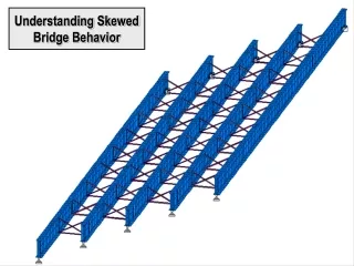
Understanding Skewed Bridge Behavior
630 likes | 667 Vues
Explore the impact of crossframe effects on skewed bridge behavior using a test case with a 60° skew and 150 ft span. Analyze differential deflections with and without crossframes to identify design challenges and solutions for accurate modeling. Understand the importance of crossframe interaction in predicting structural behavior and optimizing bridge performance.

Understanding Skewed Bridge Behavior
E N D
Presentation Transcript
Skewed Bridge Behavior • Out-of-plane effects occur in skewed bridges that cannot be predicted by one-dimensional (line girder) analysis methods. • AASHTO/NSBA “Guidelines for Design for Constructability” identifies two separate issues: • Intermediate Crossframe Effects • End Crossframe Effects • Both Intermediate and End Crossframe Effects will be examined using a test case.
Test Case: • 60° Skew, 150 ft Span • FRAMING PLAN • TRANSVERSE SECTION
Mz Line Girder Model: Analysis of Test Case, Line Girder Model: • We will conduct an initial analysis of the test structure using a Line Girder Model. • This is the most commonly used analysis method for non-complex bridges, and is used by many common software packages. (MDX, Merlin Dash, BARS-PC) • Each girder is modeled independently, with crossframe effects ignored.
Line Girder Analysis Results Crossframe Effects Ignored • Test Structure, Deflection Due to Deck Weight
Line Girder Analysis ResultsCrossframe Effects Ignored • Test Structure, Deflection Due to Deck Weight 6 Crossframe Locations 5 4 3 Deflection (in) 2 G5 G4 G3 G2 G1 1 0 0.00 50.00 100.00 150.00 200.00 Length (ft) • Results Show: • Large differential deflections between interior and exterior girders • Abrupt changes in differential deflection across the width of the bridge
Line Girder Analysis Results Crossframe Effects Ignored Test Structure, Differential Deflections at Crossframe Locations:
Line Girder Analysis ResultsCrossframe Effects Ignored D D Framing Plan Differential Deflection (in) Girder Deflection (in) Section D-D Deflections Exaggerated x 12
Line Girder Analysis Results Crossframe Effects Ignored Differential Deflection (in) Girder Deflection (in) Section A-A Deflections Exaggerated x 12 • Problem: If the girders are assumed to stay vertical, the crossframes will not permit differential deflections of this magnitude. • Conclusion: Crossframe interaction needs to be included to accurately model structure behavior.
Intermediate Crossframe Effects • We will now use a refined method to analyze the test structure with crossframe effects included. • All intermediate crossframes are fully connected during the deck pour (no slotted holes). • The end crossframes will be removed in order to isolate intermediate crossframe effects. • The behavior of the bridge will be examined under wet concrete load only. • FRAMING PLAN
ODOT Standard Crossframe: • Typical crossframes restrain girders against differential deflection and differential twist.
Lengthened Shortened • Differential vertical deflection causes crossframes to deform if the girders do not twist. • Large forces are needed to create axial deformations in the crossframe members, so resistance to this type of deflection is very high.
Undeformed Undeformed • Twisting of the girders allows differential deflection to occur without deforming the crossframe. • Generally, the torsional stiffness of the girders is low compared to the stiffness of the crossframes, so this behavior is dominant.
Analysis of Test Case, Refined Model: • In order to include crossframe effects in the analysis, we will need to use a Refined Model. • Refined Model is a general term we will use to refer to any analysis that includes both the girders and the crossframes. • Refined Models will be discussed in more detail in another presentation. Refined Model:
Refined Analysis Results Intermediate Crossframe Effects Included • Test Structure, Deflection Due to Deck Weight Crossframe Locations • Results Show: • More uniform differential deflection across the width of the bridge at crossframe locations (compared to line girder analysis)
Test Structure, Deflection Due to Deck Weight Line Girder Analysis ResultsCrossframe Effects Ignored Refined Analysis Results Intermediate Crossframe Effects Included
Refined Analysis Results Intermediate Crossframe Effects Included Test Structure, Differential Deflections at Crossframe Locations:
Refined Analysis ResultsIntermediateCrossframe Effects Included D D Framing Plan Differential Deflection (in) Girder Deflection (in) Section D-D Deflections Exaggerated x 12
Differential Deflection (in) Line Girder Analysis ResultsCrossframe Effects Ignored Girder Deflection (in) Section D-D Differential Deflection (in) Refined Analysis ResultsIntermediate Crossframe Effects Included Girder Deflection (in) Section D-D Deflections Exaggerated x 12
Deflected Shape Due to Intermediate Crossframe Effects • The analysis results show that intermediate crossframe effects cause girder twist in skewed structures. • The next several slides will step though the deflection of the test structure at each crossframe location.
Deflected Shape Due to Intermediate Crossframe Effects (Refined Analysis): A A Differential Vertical Deflection (inches) Section A-A Deflections Exaggerated x 12
Deflected Shape Due to Intermediate Crossframe Effects (Refined Analysis): B B Differential Vertical Deflection (inches) Section B-B Deflections Exaggerated x 12
Deflected Shape Due to Intermediate Crossframe Effects (Refined Analysis): C C Differential Vertical Deflection (inches) Section C-C Deflections Exaggerated x 12
Deflected Shape Due to Intermediate Crossframe Effects (Refined Analysis): D D Differential Vertical Deflection (inches) Section D-D Deflections Exaggerated x 12
Deflected Shape Due to Intermediate Crossframe Effects (Refined Analysis): E E Differential Vertical Deflection (inches) Deflections Exaggerated x 12 Section E-E
Deflected Shape Due to Intermediate Crossframe Effects (Refined Analysis): F F Differential Vertical Deflection (inches) Section F-F Deflections Exaggerated x 12
Deflected Shape Due to Intermediate Crossframe Effects (Refined Analysis): G G Differential Vertical Deflection (inches) Section G-G Deflections Exaggerated x 12
Deflected Shape Due to Intermediate Crossframe Effects (Refined Analysis): H H Differential Vertical Deflection (inches) Section H-H Deflections Exaggerated x 12
Deflected Shape Due to Intermediate Crossframe Effects (Refined Analysis): J J Differential Vertical Deflection (inches) Section J-J Deflections Exaggerated x 12
Deflected Shape Due to Intermediate Crossframe Effects (Refined Analysis): K K Differential Vertical Deflection (inches) Section K-K Deflections Exaggerated x 12
Deflected Shape Due to Intermediate Crossframe Effects (Refined Analysis): L L Differential Vertical Deflection (inches) Section L-L Deflections Exaggerated x 12
Deflected Shape Due to Intermediate Crossframe Effects (Refined Analysis): M M Differential Vertical Deflection (inches) Section M-M Deflections Exaggerated x 12
Animation of Deflection Under Wet Concrete Load with Intermediate Crossframe Effects Included (Exaggerated Scale):
Deflected Shape Under Wet Concrete Load with Intermediate Crossframe Effects Included (Exaggerated Scale):
Girder Twist due to Intermediate Crossframe Effects Definition of Girder Twist f: Forward Sign Convention: (+ Clockwise, Looking Forward - Counterclockwise, Looking Forward) • In a single span skewed structure, twist is generally highest at the supports. • End twist for the test case is shown below. • Test Structure, Refined Analysis, Intermediate Crossframes Only:
Support Reactions due to Intermediate Crossframe Effects • Intermediate crossframe effects cause vertical support reactions to be concentrated at the obtuse corners of a skewed structure. • Significant redistribution of reactions occurs throughout the structure. • HIGH REACTIONS
Support Reactions Due to Wet Concrete Weight, Refined Analysis: Forward Bearings (Exp.) Rear Bearings (Fixed) Rear Bearings (Fixed) Forward Bearings (Exp.)
Undeformed Undeformed • Conclusions for Intermediate Crossframe Effects: • There are natural differences in dead load deflections at opposite ends of intermediate crossframes in skewed structures. • Differential deflections occurring at intermediate crossframe locations cause girders to twist. • Intermediate crossframe effects must be included in analysis of highly skewed structures in order to accurately predict behavior.
End Crossframe Effects • End crossframes produce twisting effects that are independent of the intermediate crossframe behavior. End Crossframe End Crossframe: End Armor Diagonals Bottom Chord
PLAN VIEW • End Crossframe Effects • To illustrate end crossframe behavior, we will examine a 2-girder structure with end crossframes only (no intermediate bracing).
2-Girder Structure: • The end crossframe is oriented on the skew and connects the bearing points of the adjacent girders. PLAN VIEW (PARTIAL) ISOMETRIC VIEW (PARTIAL)
2-Girder Structure: ISOMETRIC VIEW (PARTIAL) • The end diaphragm can be thought of as a pair of rigid links connecting the top flange of one girder to the bottom flange of the adjacent girders.
Deflection of a Cambered Girder: • When a girder deflects, the top flange moves longitudinally relative to the bottom flange at the beam ends. We will define this distance as∆.
2-Girder Structure: GIRDER A GIRDER B Dx PLAN VIEW (PARTIAL) • The end crossframe of a skewed structure restrains the longitudinal translation of the top flange.
2-Girder Structure: GIRDER A GIRDER B Dx Dy PLAN VIEW (PARTIAL) • The end crossframe forces the top flange to move radially about the adjacent bearing point. The resulting motion produces twist in the girders.
2-Girder Structure: GIRDER A Dx Dy GIRDER B PLAN VIEW (PARTIAL) • A similar effect occurs in the adjacent girder
2-Girder Structure: GIRDER A Dx Dy GIRDER B Dx Dy PLAN VIEW (PARTIAL) • The movement of the top flange is approximately perpendicular to the centerline of bearings.
End Crossframe Effects • We will now perform a refined analysis of the test structure with end crossframe effects included. • All end crossframes are fully connected during the deck pour (no slotted holes). • The intermediate crossframes will be removed in order to isolate end crossframe effects. • The behavior of the bridge will be examined under wet concrete load only. • FRAMING PLAN
Girder Twist Due to End Crossframe Effects: • By cutting sections along the length of the bridge it can be shown that the twist caused by end crossframe effects is very similar to that caused by intermediate crossframe effects. D D • Framing Plan • Section D-D
Girder Twist Due to End Crossframe Effects: • By cutting sections along the length of the bridge it can be shown that the twist caused by end crossframe effects is very similar to that caused by intermediate crossframe effects. J J • Framing Plan • Section J-J