Download
1 / 22
220 likes | 292 Vues
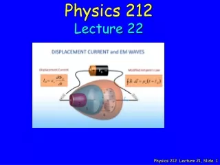
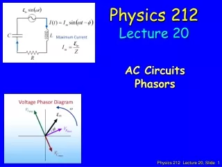
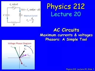
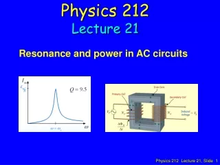
Physics 212 Lecture 21. Resonance and power in AC circuits. I max X C. I max X L. C. I max X L. e max. w. L. X L = w L. R. X C = 1/ w C. I max R. I max R. I max X C. e max = I max Z. I max (X L -X C ). I max R. X L -X C. f. R. Peak AC Problems. 07. C. L. R.

E N D
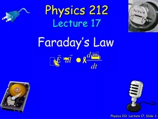
Physics 212 Lecture 21 Resonance and power in AC circuits
Imax XC Imax XL C Imax XL emax w L XL = wL R XC = 1/wC Imax R Imax R Imax XC emax = Imax Z Imax(XL-XC) Imax R XL-XC f R
Peak AC Problems 07 C L R XL R XC • “Ohms” Law for each element • PEAK values • Vgen = Imax Z • VResistor = Imax R • Vinductor = Imax XL • VCapacitor = Imax XC • Problem A generator with peak voltage 15 volts and angular frequency 25 rad/sec is connected in series with an 8 Henry inductor, a 0.4 mF capacitor and a 50 ohm resistor. What is the peak current through the circuit?
Peak AC Problems 12 C L R XL R XC • “Ohms” Law for each element • Vgen = I Z • VResistor = I R • Vinductor = I XL • VCapacitor = I XC • Typical Problem A generator with peak voltage 15 volts and angular frequency 25 rad/sec is connected in series with an 8 Henry inductor, a 0.004 Farad capacitor and a 50 ohm resistor. What is the peak current through the circuit? Which element has the largest peak voltage across it? A) Generator E) All the same. B) Inductor C) Resistor D) Capacitor
Peak AC Problems 14 C L R XL XL Z25 Z20 R R XC XC • “Ohms” Law for each element • Vgen = I Z • VResistor = I R • Vinductor = I XL • VCapacitor = I XC • Typical Problem A generator with peak voltage 15 volts and angular frequency 25 rad/sec is connected in series with an 8 Henry inductor, a 0.4 mF capacitor and a 50 ohm resistor. What is the peak current through the circuit? What happens to the impedance if we decrease the angular frequency to 20 rad/sec? A) Z increases B) Z remains the same C) Z decreases (XL-XC): (200-100) (160-125)
Resonance Light-bulb Demo
Resonance XL increases with w Z = R at resonance XC increases with 1/w Z R XC XL is minimum at resonance w0 Resonance: XL = XC Frequency at which voltage across inductor and capacitor cancel R is independent ofw 10
Imax XL Imax XL Imax R Imax R Imax XC Case 1 Case 2 Imax XC Checkpoint 1a Consider two RLC circuits with identical generators and resistors. Both circuits are driven at the resonant frequency. Circuit II has twice the inductance and 1/2 the capacitance of circuit I as shown above. Compare the peak voltage across the resistor in the two circuits A. VI > VII B. VI = VIIC. VI < VII Resonance: XL = XC Z = R Same since R doesn't change
Imax XL Imax XL Imax R Imax R Imax XC Case 1 Case 2 Imax XC Checkpoint 1b Consider two RLC circuits with identical generators and resistors. Both circuits are driven at the resonant frequency. Circuit II has twice the inductance and 1/2 the capacitance of circuit I as shown above. Compare the peak voltage across the inductor in the two circuits A. VI > VII B. VI = VIIC. VI < VII Voltage in second circuit will be twice that of the first because of the 2L compared to L
Imax XL Imax XL Imax R Imax R Imax XC Case 1 Case 2 Imax XC Checkpoint 1c Consider two RLC circuits with identical generators and resistors. Both circuits are driven at the resonant frequency. Circuit II has twice the inductance and 1/2 the capacitance of circuit I as shown above. Compare the peak voltage across the capacitor in the two circuits A. VI > VII B. VI = VIIC. VI < VII The peak voltage will be greater in circuit 2 because the value of XC doubles.
Imax XL Imax XL Imax R Imax R Imax XC Case 1 Case 2 Imax XC Checkpoint 1d Consider two RLC circuits with identical generators and resistors. Both circuits are driven at the resonant frequency. Circuit II has twice the inductance and 1/2 the capacitance of circuit I as shown above. At the resonant frequency, which of the following is true? A. Current leads voltage across the generator B. Current lags voltage across the generator C. Current is in phase with voltage across the generator The voltage across the inductor and the capacitor are equal when at resonant frequency, so there is no lag or lead.
In general Umax = max energy stored DU = energy dissipated in one cycle at resonance Quality factor Q Z
Series LCR circuit C V ~ L R (A) (B) (C) (D) X X X VR VR VL VL V V V V VL < VC if current leads generator voltage VC VC VL VL VR VR VC VC 1. The current leads generator voltage by 45o. 2. Assume V = Vmaxsinwt What does the phasor diagram look like at t = 0? V = Vmax sinwt V is horizontal at t = 0 (V = 0)
Series LCR circuit C V ~ L R At resonance (w0) Original w VL f VR VR XL increases XC decreases VL V Increase w V VC VC The current leads generator voltage by 45o How should we change w to bring circuit to resonance? (A) decrease w (B) increase w (C) Not enough info At resonance XL = XC
Series LCR circuit C V ~ L R (D) (C) (B) (A) 1. The current leads generator voltage by 45o. 2. Suppose XC = 2XL at frequency . By what factor should we increase w to bring circuit to resonance w0 ? f
Series LCR circuit C V ~ L R (A) (C) (B) Consider the harmonically driven series LCR circuit shown. At some frequency , XC = 2XL = R Vmax = 100 V R = 50 k If we change , what is the maximum current that can flow? At resonance XL = XC
C L R Circuit element: Average, over one cycle, of any periodic function : Instantaneous power P(t) = I(t)V(t) P(t) varies in time. We want the average power. For harmonically-varying functions like sin t or cos t , T = 2π/ω .
For L or C, voltage and current are /2 out of phase: I sin t, V cost t Z f XL-XC Define root mean square (RMS) R Average power for R is not zero since V and I are in phase.
Imax0L Z f XL-XC R Imax R = max Imax / 0C Average power dissipated in R for LCR circuit Maximum power delivered when = 0 … at resonance ! At resonance, 0L = 1/0C = 0
Power Transmission • If you want to deliver 1500 Watts at 100 Volts over transmission lines w/ resistance of 5 Ohms. How much power is lost in the lines? • Current Delivered: I = P/V = 15 Amps • Loss from power line = I2 R = 15*15 * 5 = 1,125 Watts! • If you deliver 1500 Watts at 10,000 Volts over the same transmission lines. How much power is lost? • Current Delivered: I = P/V = 0.15 Amps • Loss from power line = I2R = 0.15*0.15*5 = 0.113 Watts DEMO
Transformer Faraday’s Law: VP = d P /dt = NP B VS = d S /dt = NS B How do we transform 10,000 V into 120 V for your toaster ? Time-varying voltage in primary causes time-varying B in iron-core. Flux per turn = B (Area) = B Iron core maintains same B throughout. 7200 V / 240 V Primary coil captures flux P = NP B Secondary coil captures flux S = NS B Physics 212 Lecture 21, Slide 23