Download
1 / 26
260 likes | 366 Vues
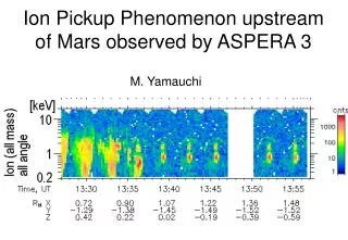
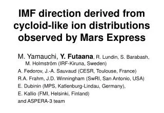
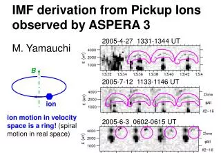
IMF derivation from Pickup Ions observed by ASPERA 3. 2005-4-27 1331-1344 UT. M. Yamauchi. B. 2005-7-12 1133-1146 UT. ion. ion motion in velocity space is a ring! (spiral motion in real space). 2005-6-3 0602-0615 UT. In-coming directions of ions. 0 3 6 9 12 15. 6. 5.

E N D
IMF derivation from Pickup Ions observed by ASPERA 3 2005-4-27 1331-1344 UT M. Yamauchi B 2005-7-12 1133-1146 UT ion ion motion in velocity space is a ring! (spiral motion in real space) 2005-6-3 0602-0615 UT
In-coming directions of ions 0 3 6 9 12 15 6 5 Electric scan 4 IMA 3 Electric scan 2 1 14 0 3 6 9 12 15 0 15 Azimuth scan Elevation scan
Viewing from +B Ion motion with V0=0 V0=0 in Martian frame means V0= -VSW in SW rest frame where E=0. simple spiral motion, ring trajectory in velocity space. VZ V*Z 3-D view B Initial velocity to B is V0cos Viewing from +E VY V*Y V*X velocity space trajectory VX V (SW frame) = V* (Martian frame) + VSW Ring 2D minimum variance direction (N) is parallel to B!
2005-4-27 , ELS (ch8) + IMA average BS average IMB Mars = 5~15 = 4 = 3 = 2 = 1 MEX orbit (light blue) during 1329-1357 UT in the cylindrical MSO coordinates. R2 = Y2+Z2. ring Mars SW
Distribution in velocity space MSO (XYZ) MVM (LMN)
Manual method vs. Automatic method Manual Automatic
However, IMA orientation is not always ideal All ch8 2005-6-3 0546-0640 UT
Viewing from +B IMA 2005-6-3 Aligned in the azi-direction (points 2, 3, 4, 5) Linear alignment (small data range in M direction) Viewing from +E =5~14=15 =1 =2 =3 =4 IMA light ion (H+ and He++), 3~8 keV
general V0≠0 case Minimum variance method gives clear L direction (// ±E), but not M & N directions. We may not use ±N as estimate of B direction, but (1) E x VSW gives BY/BZ orientation ! (2) BX/B (or ) can be obtained intuitively MAX
Check item (1) Alignment direction of the ring data by IMA ≈ Maximum variance direction (LX, LY, LZ) where LX << 1 BT=(0, BY, BZ) // VSWxE // (0, LZ, -LY) (2) Sign of B : IfL = evolution direction, then sign(BZ) = - sign(LY) (3) Tilt toward X (=) * ' = angle between max energy (MAX) direction and SW direction * Ratio k = VMAX/VSW= (MAX/SW)1/2 IfV0 = 0, two angles must be the same, i.e., ' = , and k = cos() Ifcos(') = k , most likely = '
Result Using (1)~(2) Constant IMF for 2005-4-27 event 1336-1357 UT, dawn-dusk oriented IMF, X tilt ~ 20° Using (3)~(6) Changing IMF for 2005-6-3 event 0608 UT, northward IMF, X tilt ~ +35~40°, Y tilt ~ -10° 0613 UT, northward IMF, X tilt ~ +35°, Y tilt ~ -45° 0623 UT, northward IMF, X tilt ~ +20°, Y tilt ~ -30° 0633 UT, X tilt > +40°
Procedure (1) Manually select the ring distribution. (2) Apply the minimum variance method to determine L, M, and N. Ifthe ring data is well arranged into a partial circle, ±N // B If not, (3) Examine |LX| < 0.3. If yes,L // -ESW. If not, remove the direction that corresponds to the lowest energy from the selected set of data and re-calculate a new L. (4) Manually obtain MAX and '. (5) Check if MAX /4SW ≈cos2(') is satisfied. If yes, we have ≈ ', where BX/|B| = sin(). (6)If possible, identify the evolution direction and determine the sign of L andESW. BT is parallel to VSWxESW.
Summary Approximate IMF orientation can be derived from ring-like distributed protons as measured by the IMA. The actual derivation of the ring plane is complicated (see procedure) due to the very limited viewing directions and angular resolution of the instrument.
2005-6-1 event New work (1) Beam ?
New work (2) Use magnetosheath Can we obtain "sign" of B direction? 2005-4-27 event (again)
H+ only (no He++) ! Ring H+ = 3 = 2 = 4 = 3 = 2 SW He++ SW H+
Motion of ring ions Ion motion with V0=0 VZ V*Z 3-D view B VY V*Y V*X velocity space trajectory VX V (SW frame) = V* (Martian frame) + VSW
Selected ring data : ~ 1344~1347 UT *1) L = (0.05, -0.02, 1.00) in MSO *2) M = (0.94, -0.34, -0.06) in MSO *3) N = (0.34, 0.94, -0.003) in MSO
Aligned in azimuthal direction Almost 1-D alignment Difficult to determine ring "plane"
From ring data at ~0623 UT (2005-6-3) VM (km/s) VL (km/s) VN (km/s)
Selected ring data : ~ 0608 UT *1) L = (0.06, 0.99, 0.14) in MSO *2) M = (0.79, 0.04, -0.61) in MSO *3) N = (0.61, -0.15, 0.78) in MSO
Beam-origin Alignment direction of the ring data by IMA ≈ Maximum variance direction (LX, LY, LZ) where LX << 1 BT=(0, BY, BZ) // VSWxE // (0, LZ, -LY) Sign of B IfL = evolution direction, sign(BZ) = - sign(LY) Tilt toward X (=) * ' = angle between max energy (MAX) direction and solar wind direction * Ratio k = VMAX/VSW= (MAX/SW)1/2 IfV0 = 0, two angles must be the same, i.e., ' = , and k = cos() Ifcos(') = k , most likely = ' MAX