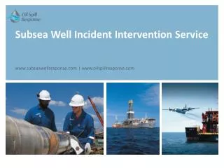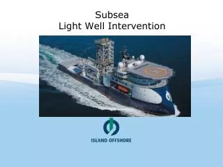
Subsea Well Intervention RPSEA Presentation October 31 st 2006
Subsea Well Intervention RPSEA Presentation October 31 st 2006 Presentation Intent To overview current intervention landscape To describe the drivers for Intervention To identify and describe the major activities and hardware within a typical Subsea Intervention

Subsea Well Intervention RPSEA Presentation October 31 st 2006
E N D
Presentation Transcript
Presentation Intent • To overview current intervention landscape • To describe the drivers for Intervention • To identify and describe the major activities and hardware within a typical • Subsea Intervention • To outline typical role of the underwater vehicle within an intervention • Etc….. • To offer input into discussion of role of Autonomous / Robotics technologies In Subsea Intervention Arena
Agenda • Well Geometry (Features Overview) – Tom Zimmerman • Subsea Well Intervention Overview – Joe Scranton • Intervention Definition / Drivers • Categorization of Intervention • Key systems overviews • The intervention vessel • The well control system • The underwater vehicle • The Subsea Intervention • Subsea vehicle duties within well intervention • ROV Tooling Overview • AUV applicability in the intervention marketplace
Surface Subsea Subsurface The Subsea landscape Floating Production Storage & Offloading Vessels Tension Leg Platforms Metering & Control Systems Surface Well Systems Light Well Intervention Subsea Drilling Systems Subsea Processing Standard Subsea Trees Subsea TemplateSystems Subsea Manifold Guidelineless Deepwater Trees Smart Well Control Systems ROV Tie-In Systems
Subsea wells under perform dry tree wells by an estimated 25% This short fall in production equates to $20.7 Billion per annum Norwegian Petroleum Directorate (NPD) estimate recovery factor improvements of 5% attributable to well intervention Prize = $5.15 Billion Per Year Economic Drivers for Intervention
Definition of Light/Medium Well Intervention “Any operation in a subsea wellbore that does not need a drilling rig to gain access to the well, to convey the service .. or .. carry out the operation!” Source: Deepstar Report 2002 However…. • Subsea wells under perform platform / dry tree wells • Cost of intervention prohibits intervention. • Lack of Subsea Christmas Tree commonality makes this task difficult The value is in the well work, the cost is in the access.
Why do we intervene Subsea wells…? • To manage the production of the well: • Maintain or Improve production levels • Repair wellbore mechanical failures • Terminate / suspend production • Via well diagnostics: • Flow characteristics • Geological data • Fluids data • Via altering the state of the well and/or well geometry: • Pro-actively(planned) or Re-actively (unplanned/failure) • Shut off unwanted water production • Reservoir Stimulation / Fracturing • Re-perforating the production intervals or establishing new intervals • Open/closing valves • Replacing parts • Removing scale or wax precipitates • Setting plugs • Etc………
What do we use to intervene the wells…? • Slicklinedeployment technology • Monofilament wire used to mechanically convey tools into wellbore. • High tensile wire spooled on and off a powered drum • Slickline = Pulling • Wirelinedeployment technology • Multi-strand cable for mechanical conveyance of tools into wellbore, as well as provide an electrical / fiber optic communication path to the operator. • High tensile cable spooled on and off a powered drum • Wireline = Pulling + Communication • Coiled Tubingdeployment technology • Rolled & Welded continuous length of steel tubing which is used to convey tools, provide communication path, as well as provide a fluid flow path. • Coiled tube spooled on and off a reel, utilizing an “Injector” system. • Tube can have integrated Wireline • Coiled Tubing = Pulling + Communication + Pushing + Pumping
What problems does being “Subsea” Create…? • Well Control is priority number one! • Safety • Hazardous working environment • Personnel Risk • Movement, Pressure, Weather, Heavy Lifts, etc • Dynamic working relationship • Between work platform (vessel) and wellhead (on seabed) • Risk of environmental release • Lack of close contact with intervention systems / tooling • Loss of senses (direct) / Feedback • HMI (Human Machine Interface)Gap • Up to 10,000ft. • Variable weather conditions • Etc…………
Typical Intervention Services Utilization Models Subsea Well Intervention (Type) Analysis • 85% of which is in well intervention • 52% is Wireline / Slickline serviceable
SchlumbergerSubsea Intervention Systems WellOPSUK Seawell • Subsea Intervention Lubricator (SIL) • Since late 80’s an excess of 250 wells intervened • Cased Hole Logging, Perforating, Slickline • Subsea Intervention System Development • 7 3/8” x 10Kpsi system designed and delivered to Caldive • For both Horizontal x Conventional Tree styles • Subsea Completion Tree (SenTREE) • Since late 1999 an excess of 200 wells intervened • 150 Additional wells committed Subsea Intervention Lubricator 7 3/8” x 10kpsi SS Int. System Large Bore SenTREE System
Intervention Genesis & Industry Firsts Flopetrol in Brazil 1970’s with a manned module for slickline First subsea intervention • BP Magnus July 1987 First field abandonment • Argyll field – Hamilton Brothers – Jan 1993 First subsea wellhead machining repair • Ellon field – Total – April 1995 First subsea Cristmas tree change out • Ivanhoe / Rob Roy field – November 1995 First subsea coiled tubing intervention • Gannet field – Shell Expro – December 1997 First recover / re-installation of an ESP Xmas tree • Gannet field – Shell Expro – January 1998 First intervention into a horizontal Xmas tree • Arkwright field – Amoco – October 1998 First deep water field abandonment(Horizontal Trees) • Cooper – EEX – August 1999 First diver less well de-commissioning operation in North sea • Tommeliten – Statoil – June 2000 2000 Onwards – Multiple Interventions (Light through heavy weight) Slb Compliant Guide System (2006…)
Subsea Intervention landscape • Water Depths shall vary: • 300 – 10,000ft(15,000ft by 2015) • Hydrocarbon pressures at the wellhead shall vary • 1,000 – 15,000 psi (20,000 psi by 2015) • A vessel shall be present • Positioned above well throughout intervention • Within +/- 100m watch circle of wellhead • +/- 100 Crew required for vessel / Intervention management • Control of well is handed over to vessel at time of intervention • Production facility shall not have control • A Subsea support vehicle(s) shall always be used • Duties dependant on SS Intervention system design. • Support vehicle(s) shall be managed from intervention vessel. • Durations shall vary (depending on WD, intervention need, etc) • Up to 2 weeks
VESSEL (C) VESSEL(A) VESSEL(B) Heavy Intervention Light intervention Medium intervention Subsea Well Intervention Well Intervention Vessel Categories
Cat C Cat A Cat B Heavy Intervention Light intervention Medium intervention • Wireline and Slickline • Benchmark 9 days/ well job $150K – 200K /day • Coiled Tubing, Wireline and Slickline • Benchmark 9 days/ well job $150K – 300K /day • Heavy Operations • Benchmark 15 days/ well job $360K – 840K/day Subsea Well Intervention Well Intervention Vessel Categories • Operations (Cat A +) Flowline Intervention Well commissioning (TCP guns+unloading) Well abandonment (P&A) Downhole Pump changeout Squeeze, acidizing or fracturing Sand or Scale cleanout Water shut-off (Plug and perf or patch) Scraping DH valve retrieval, replacement, shifting Casing leak repairs • Operations Logging (PLT’s) Light perforating Zone isolation Plug setting/removal • Operations (Cat B +) Scale milling Completion change-out/ repair Re-drill or sidetrack Xmas tree change-out
The Subsea landscape Floating Production Storage & Offloading Vessels The Vessel (Work Platform) The Subsea Vehicle (Intervention Supp.) Metering & Control Systems Surface Well Systems Tension Leg Platforms The Intervention System (Temp. Well Ctrl.) Light Well Intervention Subsea Drilling Systems Subsea Processing The Subsea Tree (Perm.Prod.Ctrl.) Standard Subsea Trees Subsea Manifold Guidelineless Deepwater Trees Smart Well Control Systems Subsea TemplateSystems ROV Tie-In Systems
Vessel Scope of Supply – Light/Medium Weight Intervention
Subsea Well Intervention – The Vessel • Provides a mobile work platform from which the Subsea Intervention activities take place. • Provides support capabilities to the operation in the form of: • Heavy Lift • Derrick and Crane • Moon Pool • Subsea Vehicles (ROV) • Tailored bed capacity (100+) • Fluids handling • Fire and Gas Systems • Vessel: • Monohull (Purpose built / DP2+) • Semi-Submersible • Size: • Monohull: 100-120m / 15,000tonnes • Semi: 4,000VDL / 24,000tonnes
Subsea Well Intervention – The Tree • Positioned on seabed, located on Subsea wellhead • Permanently (upto 25years producing life) • Provides, via control system, well control between well itself and seabed pipeline facilities • Designed and manufactured: • By multiple companies • Using industry standards. • Two dominant tree styles • Horizontal / Vertical (referring to axis that valves are located w.r.t wellbore) • Tree styles alters manor in which intervention takes place, but does not alter vehicle activities. • Size: • 4m3 x 40-60tonnes • Cost: • $3,000-$6,000k
Subsea Well Intervention – Intervention Hardware • Provides the ability to re-enter a Subsea well (on a temporary basis) with a variety of tools: • To either effect a physical change of state in well • To establish data of well condition • Establishes additional well control hardware onto well, beyond that typically resident in Subsea tree. • Allows the insertion and removal of intervention tooling into the well, whilst the well remains pressurized. • Designed and manufactured: • By multiple companies • Using industry standards. • Size: • (4mx 4m x 15m)x 40 - 60tonnes • Cost: • $6,000k to $30,000k
Intervention System Summary Subsea Lubricator Example • Subsea Stuffing Box / Grease Head • Provides environmental seal for slickline / wireline and wellbore • Retrieve-able interface for running intervention tools • Upper Well Control Head Assembly (Wireline / Slickline) • Provides well control in upper lubricator section • Incorporates tool catcher • Lubricator Section • Pressure containing section for storing wellbore tools • Length can be varied • Emergency Disconnection Assembly • Provides remotely controlled interface for separating lubricator • from Lower well control stack • Lower Well Control Assembly • Small bore BOP system to provide additional barriers to environment for • intervention activities • Contains valves/rams to cut intervention media / tools • Tree Interface Assembly / Tree Running Tool • Tree / Well specific interface • Allows LWI System to mate with well
Subsea Xmas TreeVehicle Duties within an Intervention • Survey(Visual only) • Well position establishment / Depth correlation • Leak Detection • Interface condition (prior to intervention) • Valve position verification • Connector position verification • Etc….. • Well Preparation(Varies depending on intervention) • Obstruction removal (manipulator) • Guideline / Guidewire establishment (manipulator) • Protective cover removal (manipulator) • Lift line establishment (manipulator) • Tree Cap / Wellhead Connector / etc. • Etc….. Vertical / Conventional Tree
Subsea Xmas TreeVehicle Duties within an Intervention • Well Intervention(Varies depending on intervention) • Valve Actuator Override (TDU / Piston / T-Tool) • Temporary / Permanent • Wellhead Connector Override (Hyd Jack) • Sub-assembly retrieval (Spec Tooling/ Piston / T-Tool) • Choke / Control Module / Cap / MPFM / etc…. • Lift line establishment (manipulator) • Tree Cap / Wellhead Connector / etc. • Heavy lift guidance (thrust) • Function Hot-stabbing (Hydraulically / Electrically) • Measurement • Gasket / Seal change-out (manipulator) • Surface Cleaning (manipulator / Brush / Jet) • Video Support • Etc….. Vertical / Conventional Tree
ROV use in Subsea Interventions • Pros • Power availability • Hydraulic and / or electrical • 100-500hp @ thrusters • Continuous • Communications / Control • Robust – Fiber Optic to surface control & operator • Real-time feedback • Multi-channel video • Force feedback tactility of tooling systems • Cons • Vessel Dependency • Vessel needs to be located very close to Subsea operation • Excursion limited to 10’s of meters from TMS • Tether • Limiting to freedom of vehicle within structures
Typical ROV Interfaces / Tools (Common with Intervention) • ROV Panel • Project specific interface • Mounted on side face of SS Structure allowing vehicle to dock. • Typically uses API 17D Interfaces • Small valve rotation • Hydraulic/electrical hot stabbing • Video Support • Flying Lead Orientation Tool (FLOT) • Project specific interface • For attaching/removing hydraulic/electrical connections • FLOT operations require lifting of umbilicals (100’s lbs), as well as torque/video activity. • ROV Manipulator • Electro/mechanical arm, with multiple degrees of freedom. ROV Interface panel Flying Lead Orientation Tool ROV Manipulator Arm
AUV use in Subsea Interventions • Pros • Tether-Less • No physical connection to support vessel once launched (Vessel can multi-task) • Can be launched without surface support vessel • Opens weather window of utilization • Cons • Power • Limited in power and duration of operation due to power limitations • Battery / Fuel Cell • Limited horsepower reduces ability for AUV to offer mechanical services Subsea (Push/Pull/Turn/Lift…) • Surface Vessel Proximity Dependency - Communications • Analog acoustic within 90deg comms cone from surface (Digital Spread Spectrum enhances this)
Subsea Well InterventionRPSEA PresentationOctober 31st 2006 End