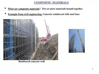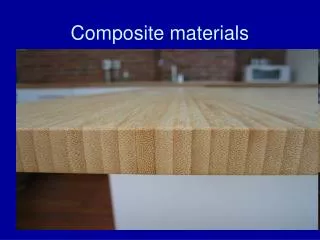
Chapter 15 Composite Materials
Chapter 15 Composite Materials. Mechanical Behavior of Materials. Reinforcement for Composites. Different types of reinforcement for composites: (a) particle reinforcement; (b) short fiber reinforcement; (c) continuous fiber reinforcement; (d) laminate reinforcement. Different Composites.

Chapter 15 Composite Materials
E N D
Presentation Transcript
Chapter 15Composite Materials Mechanical Behavior of Materials
Reinforcement for Composites Different types of reinforcement for composites: (a) particle reinforcement; (b) short fiber reinforcement; (c) continuous fiber reinforcement; (d) laminate reinforcement
Different Composites (a) Transverse section of a boron fiber reinforced aluminum composite. Vf = 10%. (b) Section of a short alumina fiber/aluminum matrix composite. (c) Deeply etched transverse section of a eutectic composite showing NbC fibers in an Ni–Cr matrix. (Courtesy of S. P. Cooper and J. P. Billingham, GEC Turbine Gnerators Ltd, U.K.)
Microstructure of a Silicon Carbide Particle Microstructure of a silicon carbide particle (10, 20, and 30%, three different volume fractions) reinforced aluminium alloy (2080) matrix composites made by hot pressing of powders followed by hot extrusion. Note the preferential alignment of SiC particles in the extrusion direction. The number and subscript p indicate the volume fraction of SiC particles in the composites. (Courtesy of N. Chawla.)
Interfacial Interaction TEM micrograph showing dislocations in aluminum in the region near a silicon carbide particle (SiCp).
Simple Composite Models Simple composite models. (a) Longitudinal response (action in parallel). (b) Transverse response (action in series).
Elastic Moduli An example of a linear increase in the longitudinal modulus of the composite, Ecl, as a function of the volume fraction of fiber for a glass fiber-reinforced epoxy. (After R. D. Adams and D. G. C. Bacon, J. Comp. Mater., 7 (1973) 53.)
Particle Reinforcement Schematic of increase in modulus in a composite with reinforcement volume fraction for a different form of reinforcement – continuous fiber, whisker, or particle. Note the loss of reinforcement efficiency as one goes from continuous fiber to particle.
Strength of Composites Determination of Vmin and Vcrit.
Strength in Silicon Carbide Whisker /alumina Composites Increase in strength in silicon carbide whisker/alumina composites as a function of the whisker volume fraction and test temperature. (After G. C. Wei and P. F. Becher, Am. Ceram. Soc. Bull., 64 (1985) 333.)
Mullite Fiber Stress vs. displacement curves for mullite fiber (Nextel 550)/mullite matrix in three-point bending. The uncoated one refers to the mullite/mullite composite with no interfacial coating, which shows a catastrophic failure. The composite with a double interfacial coating of SiC and BN shows a noncatastrophic. (Adapted from K. K. Chawla, Z. R. Xu, and J.-S. Ha, J. Eur. Ceram. Soc., 16 (1996) 293.)
Load Transfer from Matrix to Fiber Perturbation of the matrix stress state due to the presence of fiber.
Fiber and Matrix Elastic Load transfer to fiber. Variation in tensile stress σ in fiber and shear stress τ along the interface with the fiber length .
Fiber Elastic and Matrix Plastic Variation in the fiber load transfer length as a function of the aspect ratio /d
Multiple Fracture Optical micrograph of multiple fracture of tungsten fibers in an Fe–Cu matrix.
Fracture in Composites Scanning electron micrographs of fracture in composites, showing the fiber pullout phenomenon. (a) Carbon fiber polyester. (b) Boron fiber aluminum 6061.
Failure Modes in Composites Fracture of weak interface in front of crack tip due to transverse tensile stress; m and f indicate the matrix and fiber, respectively. (After J. Cook and J. E. Gordon, Proc. Roy. Soc. (London), A 228 (1964) 508.) Crack front and crack wake debonding in a fiber reinforced composite.
Interface Fracture Toughness The ratio of the interface fracture toughness to that of fiber, Gi/Gf, vs. the elastic mismatch α. Interfacial debonding occurs under the curve, while for conditions above the curve, the crack propagates through the interface.
Monolithic Material Schematic of variation in elastic moduli of a fiber composite and a monolithic material with the angle of reinforcement. Ea is the axial Young’s modulus, vat is the principal Poisson’s ratio, and Ga is the axial shear modulus.
Weibull Plot Weibull plot of tensile strength of carbon fiber/epoxy composite. (Courtesy of B. Atadero and V. Karbhari.)
Functionally Graded Materials Schematic of a functionally graded material between a ceramic on the left-hand side and a metal on the right-hand side. Also shown are micropores and additives.
ACCR Cross-section of an aluminium composite conductor reinforced (ACCR) cable. The central wires consist of continuous alumina fibers in an aluminium matrix composite while the outer wires are made of Al–Zr alloy. (Courtesy of 3M Co.)
Flexural strength for selected monolithic and laminated materials. (Adapted from M. Sarikaya, Micr. Res. Tech., 27 (1994) 371.)
PMC Schematic of a metal/polymer matrix composite (PMC) such as Arall or Glare.
Laminate with Aluminum and Silicon Carbide Cross-section of a laminate consisting of aluminium and silicon carbide: (a) SEM; (b) TEM. From X. Deng, K. K. Chawla, M. Koopman, and J. P. Chu, Adv. Eng. Mater., 7 (2005) 1.)