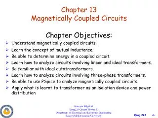
Magnetically coupled circuits
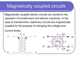
Magnetically coupled circuits. Magnetically coupled electric circuits are central to the operation of transformers and electric machines. In the case of transformers, stationary circuits are magnetically coupled for the purpose of changing the voltage and current levels. Transformer.

Magnetically coupled circuits
E N D
Presentation Transcript
Magnetically coupled circuits Magnetically coupled electric circuits are central to the operation of transformers and electric machines. In the case of transformers, stationary circuits are magnetically coupled for the purpose of changing the voltage and current levels.
Transformer • http://en.wikipedia.org/wiki/Transformer#Basic_principlse
Transformer In general, the flux produced by each coil can be separated into two components: • a leakage component denoted with ILand • a magnetizing component Im Each of these components is depicted by a single Streamline with the positive direction determined by applying the right-hand rule to the direction of current flow in the coil. Often, in transformer analysis, i2 is selected positive out of the top of coil 2, and a dot is placed at that terminal.
Flux in Transformer The leakage flux l1 is produced by current flowing in coil 1, and it links only the turns of coil 1. Likewise, the leakage flux l2 is produced by current flowing in coil 2, and it links only the turns of coil 2. The magnetizing flux m1 is produced by current flowing in coil 1, and it links all turns of coils 1 and 2. Similarly, the magnetizing flux m2 is produced by current flowing in coil 2, and it also links all turns of coils 1 and 2.
Basic Principles The transformer is a static device working on the principle of Faraday’s law of induction. Faraday’s law states that a voltage appears across the terminals of an electric coil when the flux linkages associated with the same changes. This emf is proportional to the rate of change of flux linkages. Putting mathematically: Where, e is the induced emf in volt and is the flux linkages in Weber turn.
Transformer Model Voltage Equation of a transformer in matrix form is: where r = diag [r1 r2], a diagonal matrix, and The resistances r1 and r2 and the flux linkages l1 and l2 are related to coils 1 and 2, respectively. Because it is assumed that 1 links the equivalent turns of coil 1 and 2 links the equivalent turns of coil 2, the flux linkages may be written as Where
Linear Magnetic System Reluctance is impossible to measure accurately, could be determined using:
Flux Linkage of a Coil Fig. 1 shows a coil of N turns. All these N turns link flux lines of Weber resulting in the N flux linkages. In such a case: • Where • N is number of turns in a coil; • e is emf induced, and • is flux linking to each coil
Change in Flux The change in the flux linkage can be brought about in a variety of ways: • coil may be static and unmoving but the flux linking the same may change with time • flux lines may be constant and not changing in time but the coil may move in space linking different value of flux with time. • both 1 and 2 above may take place. The flux lines may change in time with coil moving in space.
Magnetically coupled M/C In the case of electric machines, circuits in relative motion are magnetically coupled for the purpose of transferring energy between mechanical and electrical systems. Because magnetically coupled circuits play such an important role in power transmission and conversion, it is important to establish the equations that describe their behavior and to express these equations in a form convenient for analysis.
Generating Fig. 2 shows a region of length L m, of uniform flux density B Tesla, the flux lines being normal to the plane of the paper. A loop of one turn links part of this flux. The flux linked by the turn is L B X Weber. Here X is the length of overlap in meters as shown in the figure. If now B does not change with time and the loop is unmoving then no emf is induced in the coil as the flux linkages do not change. Such a condition does not yield any useful machine. On the other hand if the value of B varies with time a voltage is induced in the coil linking the same coil even if the coil does not move.
Change in Flux Linkage The magnitude of B is assumed to be varying sinusoidal, and can be expressed as: • Where • Bm is the peak amplitude of the flux density. is the angular rate of change with time. Then, the instantaneous value of the flux linkage is given by: • = N = NLXBm sin t Which of electrical machine that is applicable?
Rate of change of Flux Linkage • Instantaneous flux: Moving Coil • Instantaneous emf :
EMF induced • The Peak emf induced: • rms value of induced emf is: