Download
1 / 60
620 likes | 755 Vues
The WWiSE (World Wide Spectrum Efficiency) proposal presents a framework for next-generation WLAN technology compatible with global regulatory standards. This initiative emphasizes compatibility with existing infrastructures built on prior 802.11 amendments, focusing on performance, throughput, and efficiency. Key features include modes supporting dual transmit antennas, a maximum PHY rate of 135 Mbps, and enhancements for Quality of Service (QoS). The proposal aims to create a robust and flexible high-throughput solution that ensures seamless operation across various environments, benefiting users in home, enterprise, and hotspot settings.

E N D
WWiSE IEEE 802.11n Proposal September 16, 2004 Airgo Networks, Bermai, Broadcom, Conexant, Realtek, STMicroelectronics, Texas Instruments S. Coffey, et al., WWiSE group
Contributors and contact information • Airgo Networks: VK Jones, vkjones@airgonetworks.com • Bermai: Neil Hamady, nhamady@bermai.com • Broadcom: Jason Trachewsky, jat@broadcom.com • Conexant: Michael Seals, michael.seals@conexant.com • Realtek: Stephan ten Brink, stenbrink@realtek-us.com • STMicroelectronics: George Vlantis, George.Vlantis@st.com • Texas Instruments: Sean Coffey, coffey@ti.com S. Coffey, et al., WWiSE group
Contents • WWiSE approach • Overview of key features • Proposal description • Physical layer design • MAC features • Discussion • Summary S. Coffey, et al., WWiSE group
The WWiSE approach • WWiSE = World Wide Spectrum Efficiency • The partnership was formed to develop a specification for next generation WLAN technology suitable for worldwide deployment • Mandatory modes of the WWiSE proposal comply with current requirements in all major regulatory domains: Europe, Asia, Americas • Proposal design emphasizes compatibility with existing installed base, building on experience with interoperability in 802.11g and previous 802.11 amendments • All modes are compatible with QoS and 802.11e • Maximal spectral efficiency translates to highest performance and throughput in all modes S. Coffey, et al., WWiSE group
The WWiSE approach, contd. One solution applicable to all markets “Synergy and mutual reinforcement is only possible if the following conditions are met: • The same HT technology is able to function in all three markets and environments [home, enterprise, hotspot]– this enhances the utility of HT for the users • … ” • Wi-Fi Alliance MRD for High Throughput Technology, Nov. 2003 (doc. 11-03/879r2) S. Coffey, et al., WWiSE group
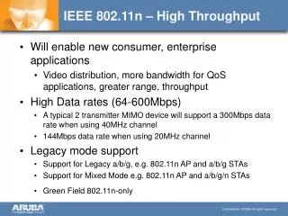
Overview of key mandatory features • The WWiSE proposal’s mandatory modes are: • 2 transmit antennas • 20 MHz operation • 135 Mbps maximum PHY rate • 2x1 transmit diversity modes, 20 MHz • Mixed mode preambles enabling on-the-air legacy compatibility • Efficient greenfield preambles – no increase in length over legacy • Enhanced efficiency MAC mechanisms • All components based on enhancement of existing COFDM PHY 2x2 MIMO operation in a 20 MHz channel: Goal is a robust, efficient, small-form-factor, universally compliant 100 Mbps mode that fits naturally with the existing installed base S. Coffey, et al., WWiSE group
Overview of key optional features • The WWiSE proposal’s optional modes are: • 3 and 4 transmit antennas • 40 MHz operation • Up to 540 Mbps PHY rate • 2x1, 3x2, 4x2, 4x3 transmit diversity modes • Advanced coding: Rate-compatible LDPC code S. Coffey, et al., WWiSE group
Insert training Add pilots FEC encoder, puncturer Interpol., filtering, limiter MIMO interleaver Symbol mapper Upconverter, amplifier IFFT D/A Add cyclic extension (guard) Transmitter block diagram S. Coffey, et al., WWiSE group
Unified format All combinations of 2, 3, 4 transmit antennas and 20/40 MHz offer exactly these 5 modes All 20 MHz modes have 54 data subcarriers, 2 pilots. All 40 MHz modes have 108 data subcarriers, 4 pilots S. Coffey, et al., WWiSE group
Advantages of unified format • Minimization of cost: • Development time, testing of modes, and interoperability are significant sources of cost • A unified basic plan simplifies these tasks • Market acceptance and growth • Faster time to market • The most straightforward scalability • Rate selection and management: • One basic plan across all antenna configurations and bandwidths S. Coffey, et al., WWiSE group
2 transmitter SDM, 20 MHz (mandatory) S. Coffey, et al., WWiSE group
2x1 modes, 20 MHz (mandatory) S. Coffey, et al., WWiSE group
Optional data modes • 20 MHz: • 3 Tx space-division multiplexing • 4 Tx space division multiplexing • 3x2, 4x2, 4x3 space-time transmit diversity • 40 MHz: (all 40 MHz modes optional) • 1 Tx antenna • 2 Tx space division multiplexing • 3 Tx space division multiplexing • 4 Tx space division multiplexing • 2x1, 3x2, 4x2, 4x3 space-time transmit diversity • LDPC code option • An option in all proposed MIMO configurations and channel bandwidths S. Coffey, et al., WWiSE group
Optional mode data rates 20 MHz: 40 MHz: S. Coffey, et al., WWiSE group
Add pilots Insert training FEC encoder, puncturer Interpol., filtering, limiter MIMO interleaver Symbol mapper Upconverter, amplifier IFFT D/A Add cyclic extension (guard) S. Coffey, et al., WWiSE group
Mixed-mode preambles: Capable of operation in presence of legacy 11a/g devices Ensure correct deferral behavior by devices compliant to legacy spec Green-field preambles: Operate in time interval or environment with only 11n devices on the air May be used with protection mechanisms, as in 11g; or with new burst mode; or in 11n-only BSS Greater efficiency than mixed-mode preambles Preambles Both preamble types are derived from a common basic structure, providing reuse in algorithms S. Coffey, et al., WWiSE group
STRN STRN STRN STRN 400 ns cs STRN 400 ns cs STRN 400 ns cs STRN 200 ns cs STRN 200 ns cs STRN 600 ns cs Short training sequence 4 Transmitters 3 Transmitters 2 Transmitters 20 MHz: STRN = 802.11ag short training sequence 40 MHz mixed mode: STRN = Pair of 802.11ag short sequences separated in frequency by 20 MHz 40 MHz green field: STRN = Newly defined sequence cs = Cyclic shift S. Coffey, et al., WWiSE group
GI2 STRN SIGNAL-N LTRN STRN 400 ns cs GI21 LTRN 1600 ns cs SIGNAL-N 1600 ns cs Long training sequence and SIGNAL-N, green-field, 2 transmitters 20 MHz: LTRN = 802.11ag long training sequence with four extra tones, 6.4 usec 40 MHz: LTRN = Newly defined sequence, 6.4 usec GI21 = GI2 for LTRN with 1600 ns cyclic shift SIGNAL-N = 54 bits, 4 usec S. Coffey, et al., WWiSE group
GI2 GI2 STRN SIGNAL-N LTRN LTRN GI21 LTRN 1600 ns cs SIGNAL-N 1600 ns cs GI21 LTRN 1600 ns cs STRN 400 ns cs GI22 LTRN 100 ns cs -GI22 -LTRN 100 ns cs SIGNAL-N 100 ns cs STRN 200 ns cs GI23 LTRN 1700 ns cs -GI23 -LTRN 1700 ns cs SIGNAL-N 1700 ns cs STRN 600 ns cs Long training sequence and SIGNAL-N, green-field, 3 and 4 transmitters For 3 transmitters, the first three rows are used S. Coffey, et al., WWiSE group
2 transmitter green-field long training and SIGNAL-N; plus short sequence if 40 MHz GI2 STRN SIGNAL LTRN GI24 LTRN -100 ns cs SIGNAL -100 ns cs STRN 400 ns cs Long training and SIGNAL fields, mixed mode, 2 transmitters S. Coffey, et al., WWiSE group
GI2 3 or 4 transmitter green-field long training and SIGNAL-N; plus short training if 40 MHz STRN SIGNAL LTRN SIGNAL -100 ns cs GI24 LTRN -100 ns cs STRN 400 ns cs GI25 STRN 200 ns cs LTRN 100 ns cs SIGNAL 100 ns cs GI26 LTRN 200 ns cs STRN 600 ns cs SIGNAL 200 ns cs Long training and SIGNAL fields, mixed mode, 3 and 4 transmitters For 3 transmitters, the first three rows are used S. Coffey, et al., WWiSE group
Configuration Short First long SIGNAL Second long Total Green-field 1x1 8 8 4 0 20 2x2 8 8 4 0 20 3x3 8 8 4 8 28 4x4 8 8 4 8 28 Preamble lengths (20 & 40 MHz) All space-time block codes follow the pattern with the same number of transmit antennas S. Coffey, et al., WWiSE group
Configuration Short First long SIGNAL Second short Second long Second SIGNAL Third long Total 1x1 8 8 4 -/8 8 4 0 -/40 2x2 8 8 4 0/8 8 4 0 32/40 3x3 8 8 4 0/8 8 4 8 40/48 4x4 8 8 4 0/8 8 4 8 40/48 Preamble lengths (20 & 40 MHz), contd. Mixed mode All space-time block codes follow the pattern with the same number of transmit antennas S. Coffey, et al., WWiSE group
Add pilots Insert training FEC encoder, puncturer Interpol., filtering, limiter MIMO interleaver Symbol mapper Upconverter, amplifier IFFT D/A Add cyclic extension (guard) S. Coffey, et al., WWiSE group
BCC encoder, puncturer To MIMO interleaver BCC encoder, puncturer Multiplexing across two encoders (round robin) Parallel encoders • For 40 MHz modes with more than two spatial streams, two parallel BCC encoders are used: Data payload S. Coffey, et al., WWiSE group
Advanced coding option • Rate-compatible LDPC code with the following parameters: • Transmitter block diagram as for BCC modes, except symbol interleaver, rate-compatible puncturing, and tail bits are not used Rate Information bits Block length 1/2 972 1944 2/3 1296 1944 3/4 1458 1944 5/6 1620 1944 S. Coffey, et al., WWiSE group
LDPC code, contd. • There is no change required to SIFS or to any other system timing parameters when the advanced coding option is used • The block size of 1944 reduces or eliminates the need for pad bits at the end of a packet • Pad bits are eliminated for 2 transmitter operation in 20 MHz channels, and 2x1 and 1x1 in 40 MHz channels • The four parity check matrices are derived from the rate-1/2 matrix via row combining • The parity check matrices are structured and based on square-shaped building blocks of size 27x27 • The parity check matrices are structured to enable efficient encoding S. Coffey, et al., WWiSE group
Add pilots Insert training FEC encoder, puncturer Interpol., filtering, limiter MIMO interleaver Symbol mapper Upconverter, amplifier IFFT D/A Add cyclic extension (guard) S. Coffey, et al., WWiSE group
Parameterized 802.11a-style interleaver 5 subcarrier shift, same interleaver Bit-cycling across NTX transmitters . . . MIMO interleaving TX 0 interleaved bits Coded bits TX 1 interleaved bits Shift of 5 additional subcarriers for each additional antenna S. Coffey, et al., WWiSE group
Add pilots Insert training FEC encoder, puncturer Interpol., filtering, limiter MIMO interleaver Symbol mapper Upconverter, amplifier IFFT D/A Add cyclic extension (guard) S. Coffey, et al., WWiSE group
AP STA Space-time block codes and asymmetry • Simple space-time block codes (STBCs) are used to handle asymmetric antenna configurations • STBC rate always is an integer - No new PHY rates result from STBC encoding of streams • Block size is always two OFDM symbols • STBC encoding follows the stream encoding S. Coffey, et al., WWiSE group
Asymmetric modes, contd. • These modes are all open-loop • No channel state information required at transmitter • No calibration required • No overhead from exchanging channel state information • No sensitivity to channel state information errors S. Coffey, et al., WWiSE group
2x1: 3x2: 4x2: 4x3: t1 t2 t1 t2 Tx 1 s1 s2 Tx 1 s1 s2 Tx 2 -s2* s1* Tx 2 -s2* s1* Tx 3 s3 s4 Tx 4 -s4* s3* t1 t2 t1 t2 Tx 1 s1 s2 Tx 1 s1 s2 Tx 2 -s2* s1* Tx 2 -s2* s1* Tx 3 s3 s4 Tx 3 s3 s4 Tx 4 s5 s6 Space-time block codes The STBC is applied independently to each OFDM subcarrier S. Coffey, et al., WWiSE group
Add pilots Insert training FEC encoder, puncturer Interpol., filtering, limiter MIMO interleaver Symbol mapper Upconverter, amplifier IFFT D/A Add cyclic extension (guard) S. Coffey, et al., WWiSE group
I R&SSMIQ AWG I Spectrum Analyzer RFFE Board Q IF Q RF (2.4 GHz) R&SSMIQ LO Power spectral density, 20 MHz • An AWG is loaded with files representing signal formats of interest. • Each file represents about 0.5 msec of randomly modulated OFDM symbols, prepended with short and long training sequences • Output of AWG is modulated using an R&S SMIQ to IF frequency • The output of the SMIQ is input to a board with RFFE+PA • The PA distorts the input spectrum, producing spectral regrowth. • The resulting spectrum is recorded on a spectrum analyzer. S. Coffey, et al., WWiSE group
56-tone OFDM signals • This is a 56 tone OFDM signal with a short trapezoidal window • The PA is operated 3.5 dB backed off from PO-1 dB compression point • The signal meets spectral mask • The “standard” 52 tone OFDM signal with same window meets mask with a backoff of 3.0 dB - S. Coffey, et al., WWiSE group
2 pilot symbols • MIMO systems have multiple receive chains, providing receive diversity • Format uses cyclic modulation of pilot symbols in time and space, for 20 MHz and 40 MHz • This provides transmit diversity gain over a static modulation • Overall the scheme provides robust synchronization with MIMO-OFDM transmission S. Coffey, et al., WWiSE group
MAC features S. Coffey, et al., WWiSE group
MAC features • The WWiSE proposal builds on 802.11e functionality as much as possible, in particular EDCA, HCCA, and Block Ack • Block Ack mandatory • Backward compatibility • Simplicity • Shorter time to standardization • Shorter time to productization • Effectiveness • Eliminate the big bottlenecks S. Coffey, et al., WWiSE group
Aggregation • Bursting and Aggregation: • MSDU aggregation • Increased maximum PSDU length, to 8191 octets • PSDU aggregation = HTP burst: • sequence of MPDUs from same transmitter • Reduced interframe spacing • 0 usec if at same Tx power level and PHY configuration • 2 usec otherwise (with preamble) • Not dependent on RA S. Coffey, et al., WWiSE group
HTP Burst No idle gap Normal ACK policy • = PPDU aggregation • Multiple RA allowed within the burst • Block Ack Request and Block Ack frames allowed within the burst • Last PSDU bit indicates to receiver that it should revert to preamble search Np Ns PSDU Ns PSDU Ns PSDU xIFS Non-normal ACK = N-Preamble Np Last PSDU bit set = N-Signal field @ robust encoding rate Ns S. Coffey, et al., WWiSE group
HTP Burst vs. MSDU Aggregation • HTP burst allows aggregation without incurring latency cost (on-the-fly aggregation) • HTP allows multiple RA per burst • HTP allows multiple rates within burst • HTP allows varying TX power within burst S. Coffey, et al., WWiSE group
Block Ack - Ack Policy • Block Ack frames now have ACK policy bits • Allows: • Normal ACK behavior per 802.11e draft • No-ACK • other settings reserved • Reduces Block Ack overhead • by eliminating explicit ACKs (as an option) S. Coffey, et al., WWiSE group
Block Ack - Ack Policy, contd. • Allows multiple RA + Block Ack Frames within a single HTP burst • if immediate ACK required: • HTP burst broken to allow SIFS + ACK • HTP burst single RA, ending with Block Ack Request + SIFS + ACK • HTP burst single RA, ending with Block Ack Request + Block Ack + ACK • without immediate ACK • HTP burst is allowed to continue • HTP burst may contain multiple Block Ack Request to multiple RA • Effectively allows additional, more efficient modes of use for Block Ack mechanism S. Coffey, et al., WWiSE group
Legacy Interaction • Legacy remediation • N-STA detection/advertisement • Identification of TGn and non-TGn devices and BSSs • Extends ERP information element • Uses proven 802.11g signaling • Legacy Protection mechanisms • Existing protection mechanisms (extended to N/G case) • Addition of PLCP length spoofing • 40/20 MHz channel switching supported • Equitable sharing of resources with legacy S. Coffey, et al., WWiSE group
Simulations • PHY model in MAC simulations • Detailed description in IEEE 802.11-04/877r3 • TGn MIMO Channel Models • Impairments as specified by FRCC • Union bound technique to estimate PHY layer frame errors • Performance closely matches full simulations for mandatory phy configurations • Binary convolutional coding • Executes as MATLAB routine called by MAC simulator in NS S. Coffey, et al., WWiSE group
EDCA Simulation Results • EDCA 2x2 – 20MHz 5GHz (max rate = 135 mbps) • QOS goals met, all flows, all scenarios • S-1: 54 Mbps (52q/1.5nq), latencies excellent • S-4: 44 Mbps (10q/34nq), latencies excellent • S-6: 47 Mbps (45q/2nq), latencies very good • EDCA 2x2 – 40MHz 5GHz (max rate = 270 mbps) • Even better, e.g. • S-1: 56 Mbps (52q/3.5nq), latencies excellent • S-4: 65 Mbps (10q/55nq), latencies excellent • S-6: 51 Mbps (45q/6nq), latencies excellent * HTP burst employed in sims, but no aggregation used S. Coffey, et al., WWiSE group
EDCA Simulation Parameters – AP/STAe.g., scenario 4 S. Coffey, et al., WWiSE group
HCCA Simulation Results • HCCA 2x2 – 20MHz 5GHz (max rate = 135 mbps) • QOS goals met, all flows, all scenarios • S-1: 80 Mbps (52q/28nq), latencies excellent • S-4: 86 Mbps (10q/76nq), latencies very good* • S-6: 63 Mbps (45q/18nq), latencies excellent • HCCA 2x2 – 40MHz 5GHz (max rate = 270 mbps) • Even better, e.g. • S-1: 110 Mbps (52q/58nq), latencies excellent • S-4: 135 Mbps (10q/125nq), latencies excellent • S-6: 70 Mbps (46q/24nq), latencies excellent *scheduler tuned too much toward BE flows S. Coffey, et al., WWiSE group
HCCA Simulation Parameters • HTP burst employed, but no MSDU aggregation used • Very simple scheduler employed • Round robin • Same TXOP value granted to all STA, regardless of flow characteristics, number of flows at STA, or priority of flows • Each STA polled once per round • No real effort put into making an intelligent scheduler • Results quite good • Could be better • Better scheduler could be used • Could employ MSDU aggregation S. Coffey, et al., WWiSE group