
RetroGame
Retro Game. 7805T = 5-volt regulator R1 – R7 & R17 = 100 Ω (brown, black, brown) R8 – R10 = 10 k Ω (brown, black, orange) R12 – R16 = 1 k Ω (brown, black, red) C1 = 10 pF – OK to leave out C2 = 1 μ F Q1 – Q5 = 2N2907 or 2N3906 IC1 = PIC16C622A or 16C620P IC2 = 74LS374N Speaker

RetroGame
E N D
Presentation Transcript
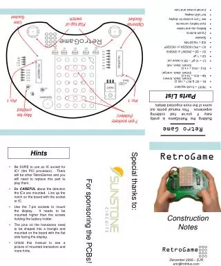
Retro Game • 7805T = 5-volt regulator • R1 – R7 & R17 = 100 Ω (brown, black, brown) • R8 – R10 = 10 k Ω (brown, black, orange) • R12 – R16 = 1 k Ω (brown, black, red) • C1 = 10 pF – OK to leave out • C2 = 1 μF • Q1 – Q5 = 2N2907 or 2N3906 • IC1 = PIC16C622A or 16C620P • IC2 = 74LS374N • Speaker • 2 push-buttons • Battery clip and holder • 2-pin battery connector • two 7-pin sockets for display • 5x7 LED display • 2 small screws and nuts Use Socket Flat top of switch Optional Socket Parts List Pin 1 Pin 1 Building the RetroGame is pretty easy if you’ve had soldering experience. This manual points out some of the more important details. May be omitted 7-pin sockets (hidden) Hints RetroGame Special thanks to: • Be SURE to use an IC socket for IC1 (the PIC processor). There will be other RetroGames and you will need to replace this part to play them. • Be CAREFUL about the direction the ICs are mounted. Line up the notch on the board with the socket or IC. • Use the 7-pin sockets to mount the display. It needs to be mounted higher than the screws holding the battery holder. • The pins on the transistors need to be shaped into a triangle and mounted on the board with the flat side facing the display. • Unfold this manual to see a picture of mounted transistors and more hints. For sponsoring the PCBs! Construction Notes RetroGame December 2006 – EJR eric@rothfus.com
RetroGame v1.1 • Make sure that the flat side of the push-buttons is facing the top of the board. • The bottom of the little speaker has + (plus) and – (minus) pins. Put the + pin in the hole closest to R17. • The display can be inserted in either orientation. There’s no “top” or “bottom” of the display. • Insert the screws for the battery holder from the bottom of the board. This makes the battery fit better. • Insert the battery clip through the hole in the bottom of the board, and tie a loose knot to keep it from falling out. More Hints