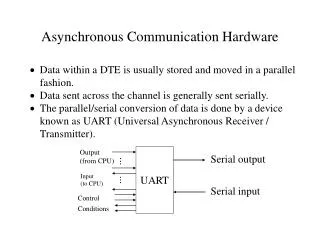
Asynchronous Serial Communication
Asynchronous Serial Communication. Peter Szyszko. Agenda. Serial Basics Async serial communication data format Async communication types RS-232 Essential FIB1-SRLM-SC002. Start. Data. Parity. Stop. 0. 5, 6, 7, 8. 1. 1, 1.5, 2. Unit: bit. Async Serial Communication Data Format.


Asynchronous Serial Communication
E N D
Presentation Transcript
Asynchronous Serial Communication Peter Szyszko
Agenda • Serial Basics • Async serial communication data format • Async communication types • RS-232 Essential • FIB1-SRLM-SC002
Start Data Parity Stop 0 5, 6, 7, 8 1 1, 1.5, 2 Unit: bit Async Serial CommunicationData Format • Start bit: Always fill “0” • Data bit: 5, 6, 7, 8 bit • Parity: None, Odd, Even, Space, Mark • Stop bit: 1, 1.5(Data bit =5), 2 bit • Data Frame Length If N, 8, 1: Data frame length is 10 bits. If E, 7, 2: Data frame length is 11 bits.
Start Start Data Data Parity Parity Stop Stop Stop Stop Parity Parity Data Data Start Start RS-232 signal definition 5V 0V +12V UART Transceiver D0 -12V …… Tx D7 Rx 5V 0V Parallel +12V TTL RS-232 -12V
RS-232 Connection Type - I • Example: PC + Null Modem cable + PC • RS-232 Signals • Short DCD with DSR to ensure all type of software works. Such as serial console port on rack server. DTE Signals Wiring DTE Signals TxD RxD RTS CTS DTR DSR DCD GND TxD RxD RTS CTS DTR DSR DCD GND
RS-232 Connection Type - II • Example: PC + Straight cable + Modem • RS-232 Signals • DCD on DCE device is generally an output signal DTE Signals Wiring DCE Signals TxD RxD RTS CTS DTR DSR DCD GND RxD TxD CTS RTS DSR DTR DCD GND
H/W Flow Control PC 2 PC 1 * RTS stop to transmit data.
S/W Flow Control 1. Xon Rx Tx PC 1 PC 2 3. Xoff 2. Start to Send Tx Rx X 4. Stop to send
3-Wire RS-232 Wiring Site A Signal Site B Signal ================================== Tx --------------------------- Rx Rx --------------------------- Tx GND -------------------------- GND
8-Wire RS-232 Wiring Site A Signal Site B Signal ================================== Tx --------------------------- Rx Rx --------------------------- Tx RTS --------------------------- CTS CTS --------------------------- RTS DTR -------------------------- DSR DSR -------------------------- DTR DCD -------------------------- DCD GND -------------------------- GND
Transmission Distance • Distance -- EIA Standard / Real World Performance