Bulloch County Fire Driver
2. Positive Displacement Pump. Have largely been replaced by centrifugal pumps for use as the main fire pump on modern apparatusCan pump air, so are still used as priming pumps for centrifugal pumps during drafting operations. 3. Positive Displacement Pump. Operate on the hydraulic law that when pressure is applied to a confined liquid, the same outward pressure is transmitted outward and equally in all directions within the liquid.

Bulloch County Fire Driver
E N D
Presentation Transcript
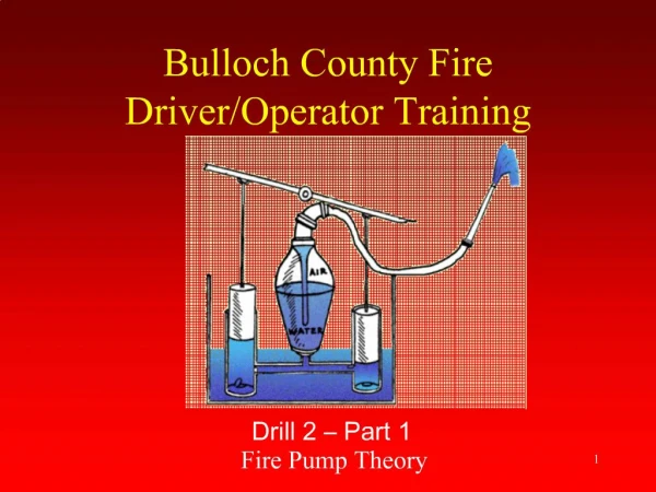
1. 1 Bulloch County Fire Driver/Operator Training Drill 2 � Part 1
Fire Pump Theory
2. 2 Positive Displacement Pump Have largely been replaced by centrifugal pumps for use as the main fire pump on modern apparatus
Can pump air, so are still used as priming pumps for centrifugal pumps during drafting operations
3. 3 Positive Displacement Pump
Operate on the hydraulic law that when pressure is applied to a confined liquid, the same outward pressure is transmitted outward and equally in all directions within the liquid
4. 4 Positive Displacement Pumps Two Basic Types:
Piston Pumps
Rotary Pumps
5. 5 Piston Positive Displacement Pumps Output determined by cylinder size and piston travel speed
Some older, large-capacity piston pumps equipped with a pressure dome or air chamber on the discharge to even out discharge surges
May be single-acting or double-acting
6. 6
7. 7 Positive Displacement Pump Double Acting Piston Pump- Pump receives and discharges water on each stroke of the piston
8. 8
9. 9 Multicylinder, high pressure piston positive displacement pump Are still used today to provide pressure up to 1,000 psi for high pressure fog lines
Are most commonly used in wildland firefighting
Require a dependable relief valve: if discharge flow is interrupted, pressure quickly build to dangerous levels
10. 10 Rotary Positive Displacement Pump Are the simplest of all fire apparatus pumps from design standpoint
Use in recent years confined to small-capacity, booster-type pumps and priming pumps
Driven by either a small electric motor or through a clutch that extends off apparatus drive shaft.
Come in two types: rotary gear pumps and rotary vane pumps
11. 11 Priming Methods and Devices Successfully drafting water depends upon the ability to create a lower pressure within the pump and the intake hose than exists in the atmosphere.
Primers fall into three categories:
Positive displacement primers
Exhaust primers
Vacuum primers
12. 12 Rotary Gear Positive Displacement Pump Total amount of water that can be pumped dependent on gear pocket size and rotation speed
Require a pressure relief valve
Are very susceptible to damage from normal wear and tear
Are very susceptible to damage form pumping contaminated water
13. 13 Rotary Vane Positive Displacement Pump Not as susceptible to damage from normal wear and tear as are rotary gear and piston types
Automatically adjust: When surface of a vane in contact with casing becomes worn, centrifugal force causes it to extend further, thus automatically maintaining a tight fit.
Most newer apparatus have �oil-less� rotary vane pumps which use water for pump lubrication.
14. 14
15. 15
16. 16
17. 17 Vacuum Primers Probably the simplest type of primer, makes use of the vacuum already present in the intake manifold of any gasoline engine.
These devices were common on older, gasoline-powered fire apparatus.
18. 18 Centrifugal Fire Pumps
19. 19 Centrifugal Pumps Nearly all modern fire apparatus use centrifugal pump as the main pump
Centrifugal pumps are classified as a nonpositive displacement pumps because they do not pump a definite amount of water with each revolution
20. 20 Centrifugal Pump Centrifugal pumps impart velocity to water and convert this velocity to pressure within pump itself
The impeller in a centrifugal pump rotates very rapidly within the casing, generally from 2,000 to 3,000 rpm
Appx. 2 times faster rpm than the engine is turning. Engine at 1000 rpm = 2000 rpm on the pump
21. 21 Centrifugal Pump To some extent, the volume capability of the pump is dependent on the size of the eye: The larger the impeller eye, the greater the flow capacity
The greater the speed of the centrifugal pump impeller, the greater the pressure developed, the increase being approximately equal to the square of the change in impeller speed
22. 22 Centrifugal Pumps Centrifugal pump has two fundamental parts:
impeller- disk transmits velocity to water
casing- container confines water to convert velocity to pressure
23. 23 Centrifugal Pump Volute- Water passage that gradually increases in cross-sectional area as it nears the pump discharge outlet
Impeller- Disk that transmit energy in the form of velocity to the water in the pump
Vane- Impeller blade that rotates about the hub and directs water flow
Shroud- Space between vanes that confines the water in its travel
24. 24 Centrifugal Pump Casing- Container that collects the water and confines it, in order to convert velocity to pressure, and then directs the water to the discharge outlet
Hub- Center of the impeller; encompasses eye an supports vanes
Eye- Place where water enters the pump
Discharge- Place where water exits pump
25. 25
26. 26 How a centrifugal pump work? A rapidly moving disc throws water introduced at its center toward its outer edge
The faster the disc is turned, the farther the water is thrown
Water velocity is converted to pressure by being confined within the container
Water, limited by the walls of the container, moves upward to the pump discharge path of least resistance
27. 27 Main factors that influence a centrifugal pump discharge pressure
Amount of water being discharge
Speed at which impeller turns
Intake pressure
28. 28
29. 29 Centrifugal Pumps The centrifugal pump depends on velocity of water to move water through the pump.
It is unable to pump air and is not self-priming.
There are two basic types of centrifugal pumps used by the fire service:
Single-stage
Two-stage
30. 30 Centrifugal Pump Single Stage Centrifugal Pump
Single impeller
Used on front-mount pumps, PTO�s, separate engine-driven and midship transfer pumps
Provides capacities up to 2,000 gpm
May have double-suction impeller to minimize the lateral thrust of large quantities of water entering the impeller eye
31. 31 Centrifugal Pump Two-stage centrifugal fire pump
Two impellers mounted in a single housing
Connects the two stages in series for maximum pressure or in parallel for maximum volume
32. 32 Two stage pumping in the pressure position All water from the manifold is directed into the eye of the first impeller, increasing the pressure and discharging 50 to 70% of the volume capacity through the transfer valve and into the eye of the second impeller
The second impeller increases the pressure and delivers the water at the higher pressure into the pump discharge port
33. 33
34. 34 Two stage pumping in the volume position Each impeller takes water from a source and delivers it to the discharge
Each impeller is capable of delivering its rated pressure while flowing 50% of the rated capacity; therefore, the total amount of water the pump can deliver is equal to the sum of each stage
35. 35
36. 36 Changeover procedure Process of switching the transfer valve on the pump between pressure and volume
When supplying greater than � to 2/3�s of pump capacity use the volume stage
Consult your operators manual for your pumps proper changeover point
Do not exceed 50 to 75psi net pump discharge pressure when changing over the pump
37. 37
38. 38 Changeover procedure Because there may be a slight interruption to fire ground operations when changeover occurs, coordinate changeover with attack crews so that lines are not shut down at critical times
Try to anticipate the requirements that will be placed on the pumper as the firefighting operation progresses, and have the transfer valve in the proper position from the start
39. 39 Changeover procedure If there is any question as to the proper operation of the transfer valve, it is better to be in parallel than in series
Know that there is a built-in safeguard that makes it impossible to accomplish manual transfer while the pump is at high pressure on many two-stage pumps, particularly on older apparatus
40. 40
41. 41 Changeover procedure Whenever possible equip the power control on power-activated transfer valves with some sort of manual override to allow the transfer to be operated should the power equipment fail
Inspect clapper valves to ensure their operation: if they stick open or closed, the pump will not operate properly in the pressure position
42. 42 Clapper Valves Are check valves that are essential in a two-stage pump.
If they stick, the pump will not operate properly in the pressure position.
Can be inspected by removing the strainer from all big intake openings, reaching into the pump with a rod, and insuring the valve swings freely.
43. 43
44. 44 Pump wear rings and packing Where the impeller shaft passes through the pump casing, packing rings are used to maintain a semi-tight seal and prevent air leaks during drafting operations
The most common materials in packing materials is made of rope fiber impregnated with graphite or lead
The packing gland can be tightened and leak control, due to packing material wear from use
45. 45 Pump wear rings and packing A very close tolerance must be maintained between the pump casing and the hub of the impeller to prevent water from escaping back into the intake
Impurities in the water supply accelerate pump wear by acting like sandpaper in wearing down metal surfaces
As the gap between the pump casing and impeller hub increases through wear, greater amounts of water escape to intake, eventually the pump is not able to supply its rated capacity
46. 46 Pump wear rings and packing To maintain the pump capacity wear rings should be replaced
Always make sure water is running through the pump to prevent overheating
Check pump temperature by placing the back of your hand on the main inlet
If pump is not needed disengage the pump
47. 47
48. 48
49. 49 Pump wear rings and packing Packing gland is adjusted so a little water is allowed to pass if not the shaft will heat up
If the shaft is scored new packing won�t fix the problem
A lantern ring is provided with the packing to provide cooling and lubrication
If the pump is operated dry for long period of time the heat will build up and damage the shaft
50. 50 Pump wear rings and packing If the pump is equipped with mechanical seals instead of packing, they will not drip and will not require adjusting
Mechanical seals are especially problematic if they freeze: The entire pump and drive assembly may need to be dissembled in order to repair and replace the seals
Do not introduce cold water into a overheated pump with these type seals